

PA1500 Anchoring Clamp - 8 kN
Glory Optical's PA1500 anchoring clamp secures aerial fiber optic cables at pole and building-facade anchor points in FTTH access networks. Its self-adjusting wedge mechanism grips the cable as line tension is applied, with a maximum tensile load of 8 kN and a choice of 9–12 mm or 10–14 mm cable-diameter ranges. The assembly combines a clamp body, wedge inserts and a wire-loop attachment, with optional laser marking for project identification.
Product line: Aerial Cable Anchoring & Dead-End Hardware
|
|
PA1500 Cable Anchor8 kN max. tensile load Grip: 9–12 mm / 10–14 mm |

PA1500 Product Photos
|
|
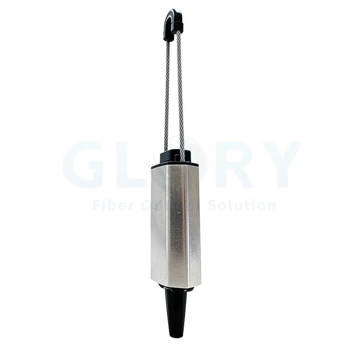
Wedge-Side Oblique ViewAngled view of the wedge side, body edges and attachment loop. |

|
|
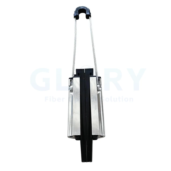
Wedge-Side ViewStraight view of the wedge assembly between the two body sides. |

|
|
Side ProfileSide view of the body and the wire-loop attachment. |

|
|
Horizontal Assembly ViewThe complete clamp shown horizontally, including the body, wedge and loop. |

|
|
Body Oblique ViewAngled view of the body face and the cable-gripping end. |

|
|
Construction DetailsComposite view of the complete clamp, side fastening point and body profile. |

PA1500 Wedge and Mounting Features
Wedge Grip That Responds to Line Tension
The wedge assembly seats around the cable and develops grip as axial tension draws it into the body. This creates the anchoring action at the cable termination point and keeps the gripping components together in one assembly.
Two Defined Cable-Diameter Ranges
Choose the 9–12 mm or 10–14 mm grip configuration for the cable being installed. Listing the selected range alongside the model gives purchasing and installation teams a clear way to separate hardware for different cable schedules.
Body-Guided Cable Contact
The outer body contains the wedge inserts and guides their position around the cable. This arrangement provides a defined gripping section at the anchor, with the cable passing through the wedge assembly toward the aerial route.
Wire-Loop Mounting Connection
The loop connects the clamp assembly to supporting hardware at a utility pole or building facade. Its position makes the attachment point visible during route planning, so the bracket connection and cable exit direction can be arranged together.
Optional Laser Identification
Laser marking can place company or network identification on the clamp body. Project text and order labels help link installed PA1500 hardware to the cable schedule, giving crews a practical reference when separate installation teams work on the same rollout.
Model and Cable-Grip Options
|
Model |
Cable outside diameter |
Maximum tensile load |
|---|---|---|
|
PA1500 |
9–12 mm |
8 kN |
|
PA1500 |
10–14 mm |
8 kN |
The two grip ranges overlap at 10–12 mm. Identify the selected configuration in the cable schedule and purchase order.
PA1500 Anchoring Clamp Technical Specifications
|
Item |
Specification |
|---|---|
|
Product name |
PA1500 anchoring clamp |
|
Product line |
Aerial Cable Anchoring & Dead-End Hardware |
|
Maximum tensile load |
8 kN |
|
Cable-diameter configurations |
9–12 mm or 10–14 mm |
|
Gripping mechanism |
Self-adjusting wedge assembly |
|
Assembly components |
Clamp body, wedge inserts and wire-loop attachment |
|
Installation points |
Utility poles and building facades with suitable anchor hardware |
|
Network role |
Mechanical anchoring of aerial fiber optic cable in FTTH access routes |
|
Identification option |
Laser marking on the clamp body |
Aerial Fiber Anchoring Applications
PA1500 Anchoring Clamp for Aerial FTTH Pole Terminations
At a pole where an aerial cable run terminates, the cable needs a mechanical anchor before it continues toward connection equipment. The PA1500 uses its wedge assembly to grip the cable and connect the termination to pole-mounted hardware through the loop. This gives the installer a defined point for transferring line tension into the supporting structure. Choose the grip version around the cable's outside diameter, then pair it with the route's design tension and anchor bracket. Record the pole position and selected clamp range in the installation schedule.
Building-Facade Cable Arrivals
A cable arriving from a street pole needs an anchor at the building side of the aerial run. Bringing span tension directly toward the entry conduit or connection point makes the mechanical arrangement harder to manage. The PA1500 places the cable grip at the facade mounting hardware, ahead of the building entry route. Its wedge body and loop form the connection between cable and support. Specify the cable diameter, chosen grip range, attachment-eye geometry and cable exit direction together, so the anchoring point fits the planned approach to the building.
Pole-Mounted Fiber Distribution Points
A distribution pole may combine an aerial approach cable with a closure, terminal or another connection node. Mechanical anchoring and optical connection serve different jobs at that location. The PA1500 holds the incoming cable at the pole hardware while the continuation follows the cable-management path toward the connection equipment. This keeps the route's anchor position identifiable on the site drawing. Include the incoming cable OD, selected grip configuration, bracket interface and project marking in the bill of materials, along with the separately specified closure or terminal mounting hardware.
Selection and Project Ordering
|
Order item |
Information for the project |
|---|---|
|
Cable information |
Cable construction, outside diameter and jacket details |
|
Grip selection |
9–12 mm or 10–14 mm; identify the chosen version on the order |
|
Route and support |
Anchor location, design tension and pole or facade hardware |
|
Mounting interface |
Loop-to-bracket connection and cable exit direction |
|
Identification |
Laser-marking text and project or network reference |
|
Delivery configuration |
Quantity, item labels and packaging arrangement |
Browse Fiber Cable Installation Hardware · Explore Outdoor Fiber Optic Cables
About Glory Optical
|
Glory Optical facility, Ningbo |
Glory OpticalFounded in 2008 · Ningbo, China · OEM/ODM support Ningbo Glory Optical Communication Co., Ltd. manufactures passive fiber optic products and supplies telecom operators, ISPs, contractors, distributors and OEM/ODM buyers. Our portfolio covers fiber boxes, splice closures, PLC splitters, fiber optic cables, patch cords, pigtails, adapters, MTP/MPO assemblies and installation accessories for fiber network projects. Manufacturing & OEM/ODM SupportManufacturing capabilities across our product families include mold development, enclosure molding, component assembly and fiber cable assembly. OEM/ODM projects can cover drawings, product configuration, samples, branding, labels and packaging, according to the selected product and confirmed requirements. |

Testing Capabilities
Glory Optical supports inspection and testing according to confirmed product specifications and order requirements. The following videos show examples from our testing activities.
Water Spray Testing |
Sealing Performance Testing |
Water Resistance Testing |
Project Supply & OEM Support
For PA1500 orders, send the cable outside diameter, selected grip range, bracket interface and marking text. Glory Optical can discuss samples, project labels and packaging around the selected configuration.
Discuss Your Product or Project Requirement
Send the product model, quantity, application and required configuration for quotation or sample discussion. Include any drawing, labeling, packaging and documentation requirements so our team can review the order details.
Email: sales@gloryoptic.com
Hot Tags: pa1500 anchoring clamp, China pa1500 anchoring clamp manufacturers, suppliers, factory, fiber optic connector tool, fiber optic connector tool kits, fiber optic termination tool kit, fiber tool box, fo cable splicing kit, tool kit fiber optic