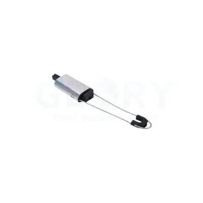

Feeder Cable Clamp for Telecom Towers
Glory Optical's feeder cable clamp secures and organizes cable runs on telecom towers, rooftop structures and building mounting points. It combines stainless steel hardware, profiled rubber cable contact and dual-nut fastening, with a 3000 N compression-load specification. Two cable-contact sizes suit 4–7 mm or 9–14 mm cable diameters, while SS201 and SS304 metal options serve different project specifications. The assembly provides local fixation for feeder, coaxial and fiber cables along supported routes.
|
|
Keep Feeder Runs Aligned at the Mounting PointProduct line: Telecom Cable Clamps & Installation Accessories Profiled rubber contact blocks grip the cable jacket, while the metal bracket and threaded fasteners connect the assembly to the supporting structure. 3000 N compression load · 4–7 mm / 9–14 mm · SS201 / SS304 |

Cable Contact, Fastening and Material Options
Two Cable-Contact Sizes
The clamp is offered in 4–7 mm and 9–14 mm diameter configurations. Each uses a cable-contact insert sized for its range, giving projects a practical way to group smaller round cables and larger feeder runs into separate installation schedules.
Profiled Rubber Grip
A micro-tooth profile on the rubber contact surface provides grip around the cable jacket. The insert separates the cable from the surrounding metal hardware and distributes contact through the clamping area, supporting orderly fixation at the mounting point.
Main Nut and Lock Nut
The threaded fastening assembly uses a main nut and a second locking nut. Together, they secure the clamp setting on the mounting hardware. The accessible fasteners also allow the assembly to be released and repositioned during cable-route changes.
SS201 and SS304 Metal Options
Choose SS201 or SS304 stainless steel components to match the project's material specification. The metal bracket and fasteners provide the structural connection, while the rubber insert handles cable contact. Both material options retain the same cable-fixation function.
Mounting-Hole Options
Standard mounting-hole options are 6 mm, 8 mm and 10 mm. Selecting the hole size with the support hardware keeps the clamp interface consistent across tower members, wall brackets and cable-management structures used on the installation.
Single and Grouped Cable Arrangements
Single-cable and multi-cable versions organize parallel runs at one support location. Two-, three- and four-cable arrangements let the installation follow the site's cable grouping, with the contact size and stainless steel grade selected for each group.
Cable Diameter Configurations
|
Configuration |
Cable outside diameter |
Cable selection |
|---|---|---|
|
Small-diameter configuration |
4–7 mm |
Round fiber, drop and jumper cables within this diameter range |
|
Larger-diameter configuration |
9–14 mm |
Feeder, coaxial and ADSS cables within this diameter range |
Feeder Cable Clamp Technical Specifications
|
Item |
Specification |
|---|---|
|
Product type |
Feeder cable clamp |
|
Installation role |
Cable fixation along supported tower, rooftop and building cable routes |
|
Compression load |
3000 N |
|
Cable diameter options |
4–7 mm or 9–14 mm |
|
Metal components |
SS201 stainless steel; SS304 option |
|
Cable-contact insert |
Rubber with a profiled micro-tooth contact surface |
|
Fastening |
Threaded assembly with main nut and lock nut |
|
Operating temperature |
−40°C to +70°C |
|
Standard mounting-hole options |
6 mm, 8 mm or 10 mm |
|
Clamp body length |
Approximately 80 mm; varies by configuration |
|
Clamp body width |
Approximately 50 mm; varies by configuration |
|
Unit weight |
Approximately 100–150 g; varies by configuration and material |
Typical Cable Routing & Support Applications
General application references for feeder routing, outdoor antenna sites and indoor cable supports.
|
|
Grouped Feeder Cables at the MastFeeder cables are grouped by clamp blocks beside the mast connection point. The view shows the contact blocks, fastening hardware and supporting structure within the cable route. |

|
|
Telecom Pole and Equipment ShelterAntenna equipment, a shared utility pole and an equipment shelter form this outdoor mobile site. The overall view puts the cable route and fixing positions in context. |

|
|
Indoor Cable Trays and Shared RoutesParallel cables follow an overhead tray through the building. The installation shows how cable grouping and support points fit within the available ceiling space. |

Configuration and Project Supply
|
Order item |
Configuration details |
|---|---|
|
Cable-contact size |
4–7 mm / 9–14 mm |
|
Stainless steel grade |
SS201 / SS304 |
|
Mounting interface |
6 / 8 / 10 mm hole options; project mounting pattern |
|
Cable grouping |
Single-cable and multi-cable arrangements; 2-, 3- and 4-cable variants |
|
Project identification |
Labels, order identification and packaging details |
For pricing and samples, send Glory Optical the cable outside diameter, stainless steel grade, mounting-hole size, cable grouping and order quantity. Include the support layout when the project uses a specific mounting pattern.
Explore Cable Clamps & Installation Hardware
About Glory Optical
|
Glory Optical facility, Ningbo |
Glory OpticalFounded in 2008 · Ningbo, China · OEM/ODM support Ningbo Glory Optical Communication Co., Ltd. manufactures passive fiber optic products and supplies telecom operators, ISPs, contractors, distributors and OEM/ODM buyers. Our portfolio covers fiber boxes, splice closures, PLC splitters, fiber optic cables, patch cords, pigtails, adapters, MTP/MPO assemblies and installation accessories for fiber network projects. Manufacturing & OEM/ODM SupportManufacturing capabilities across our product families include mold development, enclosure molding, component assembly and fiber cable assembly. OEM/ODM projects can cover drawings, product configuration, samples, branding, labels and packaging, according to the selected product and confirmed requirements. |

Testing Capabilities
Glory Optical supports inspection and testing according to confirmed product specifications and order requirements. The following videos show examples from our testing activities.
Water Spray Testing |
Sealing Performance Testing |
Water Resistance Testing |
Project Supply & OEM Support
Share the cable diameter, mounting arrangement and material specification with Glory Optical. Our team can discuss the assembly drawing, sample requirements, product identification and packaging for your project.
Discuss Your Product or Project Requirement
Send the product model, quantity, application and required configuration for quotation or sample discussion. Include any drawing, labeling, packaging and documentation requirements so our team can review the order details.
Email: sales@gloryoptic.com
Hot Tags: feeder cable clamp, China feeder cable clamp manufacturers, suppliers, factory, fiber optic connector tool kits, fiber optic termination tool kit, fiber splicing tool, fiber tool, fiber tool box, fo cable splicing kit