Introduction: Beyond the Spec Sheet
Forget abstract promises about speed. In a live data center, the cabling isn't about theoretical bandwidth; it's about the physical reality of heat, space, and human hands. The old racks of single fiber patch cords, a colorful but chaotic forest, created bottlenecks we couldn't afford. I've seen technicians spend half an hour tracing a single fault through that maze while a system alarm blared. The shift to structured, high-density cabling using MTP/MPO systems and modular panels wasn't just an upgrade; it was a move from artisanal craft to repeatable, reliable engineering. This is the foundation that makes 40G, 100G, and the march beyond not just possible, but manageable.
MTP/MPO: Not Just a Connector, a Philosophy

Calling an MTP/MPO connector a "dense" connector undersells it. It's a system in a plug. Holding 12, 16, or 24 fibers in a housing not much larger than a standard SC, it represents a fundamental design shift. The distinction matters: MPO is the generic standard (Multi-fiber Push-On), while MTP is a specific, superior implementation from US Conec, known for its precision and durability-a detail that becomes critical during thousands of mating cycles.
The real-world advantage isn't just density; it's predictability. In a 100G-SR4 deployment, which requires 8 fibers, you're no longer handling, labeling, and routing four separate LC duplex pairs. You're handling one object. On a 3 a.m. deployment, with caffeine wearing off, the reduction in error potential is tangible. The factory-terminated trunk cables that use these connectors arrive with tested, polished ends. I recall a project where we ran 144 fibers between floors using twelve 12-fiber MTP trunks. What would have been a week of termination work for two engineers was completed in an afternoon. The time saved wasn't just about labor; it was about getting revenue-generating equipment online faster.
Patch Panels: Where the System Earns Its Keep
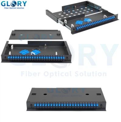
A patch panel is often seen as a passive piece of metal. In practice, it's the central nervous system of your physical layer. The difference between a standard LC panel and a high-density modular panel is the difference between a static bookshelf and a library with a sliding ladder. The latter is designed for active, ongoing use.
The critical component is the cassette, or module. This is the translator between the high-density backbone and the equipment world. A single cassette, for example, takes one 12-fiber MTP from the back and presents 6 duplex LC ports on the front. The choice here is strategic. A fixed-connector panel locks you in. A modular system from a vendor like Panduit or Corning allows you to adapt. Need to change from LC to SC for a legacy storage array? Swap the cassette. Need to upgrade to a 24-fiber backbone for future 400G? The frame remains; you change the internals. I've witnessed the cost-saving of this approach first-hand during a phased upgrade, where existing panel frames survived three generations of technology refresh.

Polarity: The Silent Installer Trap
Polarity is the most commonly misunderstood and botched aspect of MPO deployment. The concept is simple: light must transmit from a Tx port on one end to an Rx port on the other. With 12 identical fibers in one connector, achieving this requires a deliberate crossover scheme, defined by TIA-568 as Methods A, B, and C.
The theory is clean; the practice is where failures happen. The trap is inconsistency. You might purchase Method B trunk cables, but accidentally install Type A cassettes. The link will be dead, and the fault is invisible to the eye. I once spent a frustrating day troubleshooting a new 40G link only to find the polarity was flipped at the cassette because the installer didn't verify the type stamped on the housing.
From the field, Method B has emerged as the de facto standard for its simplicity: the "flip" is done once, inside the trunk cable. Patch cords are always straight-through. This consistency reduces cognitive load. The rule is absolute: before you plug anything in, verify the method on the trunk cable label, the cassette, and your design document. Your light meter will thank you.
Integration: A View from the Rack
Let's walk through a real deployment sequence, the way it actually happens. You're connecting a new row of top-of-rack switches to a core aggregation panel 30 meters away.
First, you install the high-density patch panel frames in both locations. You then pull the pre-terminated MTP trunk cables-these are thick, robust cables with protective pulling eyes. You route them through overhead tray or under-floor conduit, connecting the back of Panel A to the back of Panel B. This is your permanent, protected backbone. No fusion splicers on site.
Next, you populate the panels with cassettes matching your chosen polarity. You hear a solid click as the MTP connector mates into the cassette at the rear. On the front, you now have a clean, labeled array of LC ports. Finally, you use short, color-coded LC duplex patch cords to connect these front ports to the specific switch or server ports. The entire link is now live.
The operational benefits are profound. Troubleshooting is isolated: if a link fails, you replace the short, accessible front-end patch cord first. Scaling is logical: adding a new switch means using more ports on an existing cassette, or sliding in a new one. The cable management is inherent, not an afterthought. Airflow, often an afterthought in cabling, improves dramatically because the thick, permanent trunks are neatly routed at the rear, and the front uses only necessary short jumpers.
Implementation: Lessons from the Field
Planning on paper is one thing; installing in a crowded, noisy data center is another. Here is what years of deployments have solidified as non-negotiable:
Design with Slack, Not Just Space
Leave 70% fill in panels, but also design explicit slack loops for trunk cables. A service loop, neatly coiled and secured within the vertical manager, is insurance against future rack moves or accidental tugs.
Polarity as Religion
Document your chosen method (again, B is recommended) in the Run Book. Then, physically label every trunk cable end and cassette tray with "Method B" using a permanent marker. Visual redundancy prevents errors.
Bend Radius is a Law, Not a Guideline
Sharp bends cause "macro-bending" loss. I've tested links that passed but were on the edge because a trunk was cinched too tight around a corner. Use smooth-radius managers everywhere.
Label for the Next Person, Not for You
Follow TIA-606-C. Your labels should be clear to someone at 2 a.m. during a crisis. Include source rack, destination rack, and circuit ID. A simple printed label is better than handwritten tape.
Dust Caps Stay On Until Connection
The interior of an unused MTP ferrule is a magnet for dust and lint. I keep a bottle of compressed air and a box of cleaning sticks in my tool kit. Every connector gets inspected with a pocket scope before mating-no exceptions.
Test Everything, Assume Nothing
Baseline testing with an Optical Loss Test Set (OLTS) is mandatory post-installation. But also test after any reconfiguration. The most common post-change issue isn't breakage, but a dirty connector from handling. Document the loss values; they're your baseline for future diagnostics.
This approach to cabling transforms it from a necessary cost into a strategic asset. It's a system that acknowledges the constraints of physics, the fallibility of human operators, and the inevitability of change. The goal isn't just to connect point A to point B today, but to build a physical layer that remains clear, adaptable, and reliable for the next engineer who opens the rack door.