Introduction

Let's talk about what makes a fiber network actually connect. Fiber optic connectors are the critical interface between your cable and your equipment. Their job is simple but vital: align the microscopic glass core of one fiber with another so light signals can pass through with minimal loss or reflection.
Getting this wrong means slow data, dropped signals, and frustrated users. Understanding the basic parts-like the ferrule that holds the fiber, and key terms like insertion loss (signal weakening at the joint)-is the first step to choosing the right part for a fast, stable network.
Why Standards Matter
Connectors need to work together no matter who makes them. That's where standards come in. In North America, the TIA/EIA-604 standard (often called FOCIS) defines the physical details for common types like LC and SC. Globally, the IEC 61754 series does the same job. These documents rule everything: the exact sizes, how the connector locks into a port, and how it must perform. For example, they set clear pass/fail limits. A typical single-mode connector must have an insertion loss below 0.2 dB and, if it's an APC type, a return loss better than 50 dB. This standardization is why you can usually plug a patch cord from one brand into a transceiver from another and expect it to work.
The Heart of the Connector: Ferrule & Polish
The ferrule is the precision-engineered center of the connector. Its material and the polish on the fiber end face are what determine performance.
Ferrule Materials
The most common material is ceramic (zirconia). It's incredibly hard, stable, and provides a superb surface for polishing. For extremely rugged environments-think factory automation or military field use-you might find metal ferrules like phosphor bronze, which can take more physical abuse.
Ferrule Sizes
There are two mainstream sizes. The classic 2.5mm diameter is used in SC, ST, and FC connectors. The smaller 1.25mm size is used in LC and MU connectors, enabling higher port density.
Polish Types
This refers to the shape and finish of the fiber's end. It controls how light exits and, crucially, how much reflects back.
PC (Physical Contact)
The fiber tip has a slight spherical curve for basic contact.
UPC (Ultra Physical Contact)
A more refined, extended polish that creates a better surface finish than PC. It results in lower back reflection (typically around -50 dB) and is the standard for most modern data and telecom links.
APC (Angled Physical Contact)
Here, the end face is polished at an 8-degree angle. This design reflects any stray light out of the fiber core instead of back down the line. APC connectors offer the best return loss (≤ -65dB). You must use APC connectors in any system sensitive to reflections, such as Fiber-to-the-Home (FTTH) networks using GPON or any fiber system carrying RF video signals for TV service. Mixing polishes here is a common installation error that causes major interference.
Connector Types: Picking the Right Tool
Each common connector type was designed with certain applications in mind. Here's how they break down in practice:
LC Connector
What it is: A small-form-factor connector with a 1.25mm ceramic ferrule. It uses a familiar push-pull latch mechanism, similar to an RJ-45 Ethernet plug but smaller.
Where to use it: This is the king of high-density applications. I specify them for virtually all new data center cabinets and network switch panels. You can fit 72 LC ports in a 1U panel versus only 36 SC ports-a massive space saver. They're also the dominant interface on modern SFP, SFP+, and QSFP transceivers.
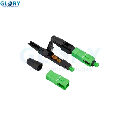
SC Connector
What it is: A connector with a 2.5mm ceramic ferrule and a simple, snap-in latch design (push to insert, pull the tab to release). It's robust and straightforward.
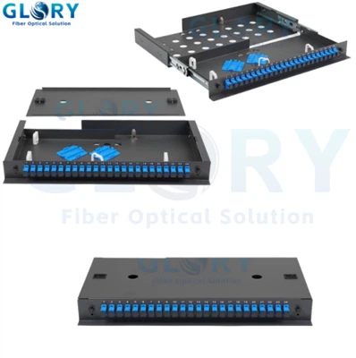
Where to use it: It's a telecommunications workhorse. You'll find it everywhere in carrier central offices, in the fiber distribution panels inside office buildings, and as the standard terminal connector for residential FTTH installations. Its simplicity makes it reliable for both technicians and end-users.
ST Connector
What it is: A connector with a 2.5mm ferrule that uses a bayonet-style lock (push and twist). It has a spring-loaded ferrule to maintain physical contact.
Where to use it: Primarily in older enterprise networks, security camera systems, and building backbones that use multimode fiber. While rugged, its twist-on design is slower to connect/disconnect than LC or SC, and it offers lower port density. I mostly encounter it when maintaining legacy infrastructure.
FC Connector
What it is: A connector that uses a 2.5mm ferrule (often high-grade ceramic) and a threaded screw-on coupling nut. This provides a very secure, vibration-resistant connection.
Where to use it: Its supreme mechanical stability makes it the preferred choice for test and measurement equipment. I won't use anything else to connect my optical time-domain reflectometer (OTDR) or light source. It's also found in high-vibration environments and some older telecom transmission equipment.
MTP/MPO Connector
What it is: This is a multi-fiber connector. A rectangular plastic ferrule holds typically 12 or 24 fibers in a single footprint. Guide pins and holes on either side ensure precise alignment between mated pairs.
Where to use it: Essential for high-speed parallel optics in data centers. A single MTP cable can support 40G, 100G, 400G, and beyond by trunking multiple fibers at once. It dramatically reduces cabling bulk and installation time for spine-leaf network architectures. Pre-terminated MTP harnesses are the only practical way to wire a large data center today.
Less Common Connector Types
Other types serve niche roles. The MU is a miniature SC, used in some very tight Japanese equipment. The E2000 includes a protective spring-loaded shutter for laser safety. SMA is a super-rugged, all-metal connector for harsh industrial/military use. Legacy types like ESCON and FDDI are largely obsolete.
How to Choose: A Practical Framework
Forget memorizing specs. Ask these questions:
What is the signal and performance need?
This decides the polish. For standard data links, UPC is fine. For any RF overlay (like cable TV) or passive optical networks (PON), you must use APC. The wrong polish will ruin performance.
How much physical space is there?
In a crowded network switch or patch panel, LC is the default choice for density. For patching in a wiring closet, SC is perfectly serviceable. For connecting rows of servers to top-of-rack switches, pre-terminated MTP harnesses are a game-changer for saving space and labor.
What is the operating environment?
A clean data center? Standard connectors are fine. A factory floor with dust and vibration? Consider ruggedized versions with shutters (E2000) or threaded couplings (FC). For a one-off field repair, a pre-polished, mechanical splice-on connector is far more practical than attempting a full epoxy/polish termination.
Installation and Testing: Non-Negotiables
A perfect connector can be ruined by poor handling. Proper procedure is everything.
Termination
Whether using epoxy-and-polish or a quick cleave tool, the fiber end face must be cleaved perfectly (within a 0.5-degree angle) and free of defects. Contamination is the enemy.
Testing
Do not skip these two steps.
Insertion Loss Verification Use a light source and power meter (LSPM) to measure the actual loss of the mated connection. For a single-mode link, anything under 0.3 dB is typically acceptable. An OTDR can also show loss per connection and locate faults.
End-Face Inspection: This is the most important and most skipped step. Use a dedicated fiber inspection microscope (per IEC 61300-3-35) to look at the ferrule. You are looking for scratches, pits, cracks, or-most commonly-dust. A single speck of dust sitting on the core can scatter light and cause significant loss. I have personally spent hours troubleshooting an intermittent link only to find a tiny contaminant visible under the scope. Clean every connector before mating, every time.
The Future
Connector evolution focuses on solving current pain points: even higher density to support 800G/1.6T interfaces, easier installation with lower latch forces and tool-less designs, and the beginnings of intelligence, with connectors potentially embedding sensors to monitor temperature, loss, or connection status in real time. The goal remains the same: move more light, more reliably, in less room.