§1Why connector selection looks settled and isn't
A "fiber connector type" question rarely fails at the catalog level. LC for density, SC for legacy and FTTH, FC for vibration benches, ST for legacy multimode, MPO/MTP for parallel optics - every vendor knows the list. The list is not where projects fail.
Projects fail at the polish/ferrule/polarity combination, at the inspection paperwork, and at contractor stocking decisions made months before the truck rolls. By the time an engineer is selecting "LC vs SC," 80% of the failure modes have already been baked in by procurement choices that nobody documented.
This note is built around three failure clusters we keep seeing on real deployments:
- Failed inspections - connector type is correct, end-face geometry or marking is non-compliant, AHJ rejects the link.
- Polarity / polish mismatches - wrong connector flavor mated against the right form factor, transceiver damage, link won't establish.
- Contractor inventory traps - too many SKUs across regions, the truck arrives with SC/APC when SC/UPC was needed, schedule slips a week waiting for the right pigtail.
What follows is the selection logic that survives those three failure modes. References to standards and operator practice are linked in line, with a consolidated reference list at the bottom.
§2The connector landscape - what's actually deployed in 2026
The connector inventory on active projects is narrower than the catalog suggests. Six families cover >95% of new deployments. Each is defined by a published IEC 61754 series sub-standard governing the physical interface geometry.
| Connector | Ferrule | Latch | IEC 61754 sub-part | Where you actually find it (2026) |
|---|---|---|---|---|
| LC | 1.25 mm | Latch (RJ-style) | 61754-20 | SFP/SFP+/QSFP-DD breakouts; high-density DC patch panels; ONT/OLT subscriber ports |
| SC | 2.5 mm | Push-pull | 61754-4 | FTTH ONT (SC/APC dominant in GPON/XGS-PON); legacy enterprise; CATV head-ends |
| FC | 2.5 mm | Threaded | 61754-13 | Test labs (OTDR launch/receive), reference jumpers, high-vibration industrial |
| ST | 2.5 mm | Bayonet | 61754-2 | Legacy OM1/OM2 multimode plant; gradually phased out; still common in MRO inventory |
| MPO / MTP | MT (12/8/24/16 fiber array) | Push-pull | 61754-7 | Data center parallel optics (40G SR4, 100G SR4, 400G DR4/SR8, 800G); pre-terminated trunks |
| Hardened / OSP (OptiTap, ODC, IP-LC, mini-SC) | Varies (1.25/2.5 mm inside hardened body) | Threaded / bayonet w/ gasket | IEC 61753-1 environmental category + vendor-specific FOCIS | FTTH drop hardening, FTTA at the radio, OSP cabinet feeders, MDU vault |
Two observations matter more than the table itself:
- Form factor is the easy half of the decision. The hard half is polish style (PC / UPC / APC), polarity convention (for MPO), and environmental category (IEC 61753 C/U/E/I) - none of which appear in the connector name.
- The catalog is not the inventory. A contractor running mixed FTTH and enterprise work needs LC/UPC, LC/APC, SC/APC, SC/UPC, plus MPO Type B trunks, plus hardened OptiTap drops. The cost of carrying that breadth is the silent driver of "we used the wrong connector" outcomes.
§3PC / UPC / APC - the polish decision that breaks transceivers
End-face polish geometry is governed by IEC 61755 and verified per IEC 61300 test methods. The three polish classes are PC (Physical Contact, mostly obsolete), UPC (Ultra Physical Contact, slight dome, blue), and APC (Angled Physical Contact, 8° angle, green).
The numbers most catalogs publish:
- UPC return loss: ≥ 50 dB typical, ≥ 55 dB for premium grade
- APC return loss: ≥ 60 dB typical, ≥ 65 dB for premium grade
- Insertion loss (both): typically ≤ 0.3 dB average, ≤ 0.5 dB maximum per Telcordia GR-326-CORE
What catalogs don't surface is the failure mode. Belden documents the mechanism plainly: mating UPC and APC connectors is not a performance compromise, it is physical damage. The flat UPC dome pressed into the 8° APC angle creates point loading at the fiber edge. Fluke Networks notes the same: a UPC-to-APC mating event can destroy the end-face - including the transceiver-side end-face of an SFP or QSFP module, which is the expensive part to replace.
Where APC is non-negotiable
Any system that carries RF over fiber, any reflection-sensitive DWDM link, and any PON with overlay video (RFoG, GPON with video). These applications are governed by the return-loss requirement, not by polish convenience:
- GPON / XGS-PON / 50G PON downstream wavelength plans interact with reflections in ways that elevate BER if return loss drops below ~55 dB. ITU-T G.984.2 sets the physical layer requirements; G.9807.1 (XGS-PON) tightens them further.
- CATV / RFoG overlays at 1550 nm - reflections become visible as ghosting on analog video carriers.
- Long-haul DWDM launch points - back-reflection into high-power transmitters drives non-linear instability.
Where UPC is the right choice
- Standard Ethernet over single-mode (1G/10G LR/ER) with no analog overlay.
- Multimode data center links (OM3/OM4/OM5) - APC is essentially never used on multimode because the modal mixing already dominates the return loss budget.
- Patch fields in enterprise IDFs/MDFs where transceivers are standard SFP/SFP+/QSFP modules with flat (UPC-mated) optical interfaces.
Mixed sites and the hybrid patch cord
When a site has SC/APC at the OLT/ONT (PON) and SC/UPC at the metro Ethernet handoff, the correct fix is not "we'll be careful." It is a hybrid patch cord - APC on one end, UPC on the other, factory-built so the polish geometry can never be wrongly mated by a technician. Stock the hybrid as a separate SKU and label it visibly. Fiber patch cord assemblies can be ordered hybrid-polished against an engineering drawing.
§4LC vs SC - the density vs accessibility tradeoff most articles get wrong
LC's 1.25 mm ferrule gives roughly 2× the port density of SC's 2.5 mm ferrule in the same panel area. Every article points this out. Few discuss the part that matters in actual operations.
The LC density penalty in MAC operations
In a 1U LC patch field at 96 duplex ports, the spacing between adjacent LC clips is small enough that fingers and bend-protected fanout boots interfere with each other. The result:
- Single-port disconnect time rises 2–4× compared to a 48-port SC panel. The technician needs to push neighboring connectors aside, hold a flashlight at a steep angle to read labels, and sometimes remove an entire bundle to access one cable.
- Adjacent port disturbance - pulling one LC frequently dislodges or partially unseats neighbors. In production data centers, this manifests as transient errors on links nobody touched.
- Fanout boot fatigue - repeated push-aside cycles stress the strain relief boot, leading to bend-radius violation and slowly rising attenuation on the disturbed fiber over months.
On hyperscale spine-leaf builds where MAC frequency is high, this drives a recurring design choice: LC at the active equipment, structured cabling on MPO/MTP trunks, breakout to LC only inside the cassette. The patch field MAC operations happen on the cassette face (lower density, accessible) while the trunk runs at MPO density.
SC's quiet advantage on OSP and FTTH
SC is not "the old one." It's still the dominant connector on the access side because three things go right:
- The 2.5 mm ferrule is mechanically forgiving - field re-terminations and outdoor splice closures tolerate handling abuse better than LC.
- SC/APC is the de facto PON connector. ITU-T G.984.2 and most operator deployment guidelines specify SC/APC at the ONT and the fiber distribution point.
- Single-snap latch release works through gloved hands at -10 °C. LC clips don't.
FC and ST in 2026 - when they still appear
FC connectors persist in test and measurement environments because the threaded coupling resists vibration drift. If a reference jumper has to maintain < 0.05 dB IL stability through a benchtop OTDR loopback over a working day, FC is still the right choice. ST shows up in legacy multimode plant - typically OM1 62.5/125 - being maintained but not extended. Contractors keep ST adapters and pigtails in MRO inventory; nobody is designing new networks around them.
§5MPO / MTP - polarity failures cost more than the cables
MPO and MTP are the same form factor (MTP is US Conec's premium-tier MPO with tighter geometry tolerances). What matters is the polarity convention, defined under TIA-568.3-D as Methods A, B, and C.
The procurement-stage failure
Polarity is determined at the design phase. The failure mode Fluke Networks documents is consistent across projects: pre-terminated MPO assemblies are made to order and typically non-returnable. Ordering the wrong polarity is not a return-and-reorder problem - it's a discard-and-reorder problem, with associated schedule loss measured in weeks.
Pin-and-socket - the other half of MPO failures
MPO connectors are male (with two alignment pins) or female (sockets receiving the pins). Active equipment MPO ports are male. Patch cords plugged into active equipment must therefore be female. The failure mode: a technician at a leaf switch plugs in a male patch cord, the pins push into the transceiver MPO interface that already has pins, and the transceiver MPO ferrule sustains damage. The economics: a $4–8 connector damages a $400–2000 transceiver.
Field-changeable polarity - when it earns its premium
US Conec's MTP PRO and Panduit's PanMPO allow the key position (and on some, the pin gender) to be changed in the field without breaking the connector. The premium per connector is significant. The justification is single-issue: if a polarity mistake at design or procurement is identified after delivery, MTP PRO converts a 1-week ordering delay into a 30-second key-flip. On schedule-critical hyperscale builds, the math works. On steady-state enterprise refresh, it usually doesn't.
§6Hardened / OSP connectors - IP rating is the requirement, not the marketing
Outside-plant connector environments are categorized by IEC 61753-1 environmental categories - C (controlled, indoor), U (uncontrolled, indoor), E (exposed, outdoor), I (industrial). The categories drive the connector body design more than the optical interface.
The dominant hardened families in 2026:
- OptiTap / SC-APC hardened (Corning origin, now multi-vendor) - FTTH drop terminals, MDU vault, IP68. Cable-side SC/APC ferrule inside an environmentally sealed housing with threaded coupling.
- ODVA-LC / IP-LC - FTTA (Fiber-to-the-Antenna) at the radio head; LC ferrule inside a hardened body, IP67/IP68.
- ODC (Huber+Suhner origin) - 2- and 7-fiber outdoor industrial use, IP68, salt-fog rated for coastal cell sites.
- Mini-SC / Pushable SC - Quick ODN pre-terminated drop cables, smaller form factor for tight outdoor termination boxes.
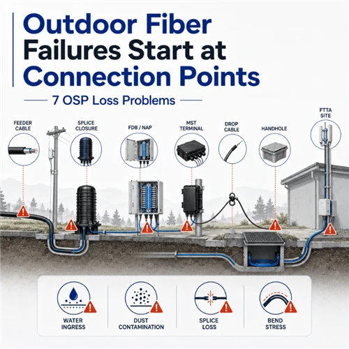
Where outdoor connector projects fail
- IP-rating mis-spec for the actual environment. A connector rated IP65 (dust-tight, water spray) deployed in a coastal site that requires IP68 (continuous immersion) plus salt fog - water ingress within 18–36 months, ferrule corrosion, link degradation.
- UV degradation on the seal gasket. Standard EPDM gaskets degrade under direct UV exposure on aerial deployments. Specifying UV-stabilized gaskets adds cost; not specifying creates 5–7 year reliability cliffs.
- Torque non-compliance at field termination. Threaded hardened connectors have a torque spec, typically 1.5–2.5 N·m. Under-torque allows moisture ingress; over-torque crushes the gasket. Without a torque wrench in the kit, neither outcome is rare.
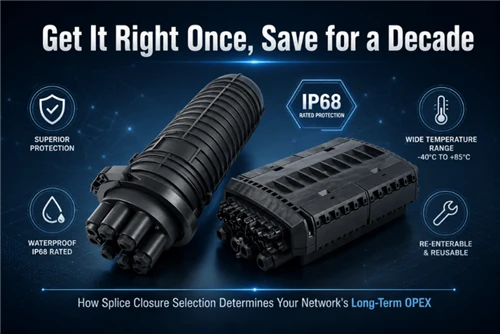
Outdoor terminations interact with fiber optic splice closures and termination boxes; the connector is one component in an IP-rated assembly, and the rating is only as good as the weakest seal.
§7Field-installable connectors - the labor math that drives the choice
Three field termination methods compete on real projects:
| Method | Time / connector | Typical IL achieved | Yield first-time pass | When it fits |
|---|---|---|---|---|
| Epoxy & polish (oven cure) | 10–15 min | 0.10–0.30 dB | ~95% | Lab, controlled, low volume |
| Mechanical (Quick) connector | 1–3 min | 0.30–0.50 dB | ~75–85% (depends on cleaver quality) | FTTH drop, fast field, lower budget |
| Splice-on connector (SOC) with fusion splicer | 3–5 min (plus splicer setup) | 0.10–0.20 dB | ~95–98% | Higher-value links, where IL margin matters; technicians already carry a fusion splicer |
The hidden cost of mechanical connectors
Mechanical (quick) connectors look like the obvious choice for high-volume FTTH drop work. They are - but with caveats that don't appear in vendor datasheets:
- Cleaver quality dominates yield. A worn cleaver blade (past ~10,000 cleaves) produces angled or hackled end-faces that push IL into the 0.6–1.0 dB range. Operators who don't track cleaver cycle count see field rejection rates climb gradually over 6–12 months.
- Index-matching gel migration. Mechanical connectors rely on gel between the field fiber and the factory stub fiber. Gel can migrate under temperature cycling, especially in outdoor or attic installations. Failures manifest 1–3 years post-install as gradual IL drift.
- Re-termination penalty. Many mechanical connector designs are single-use. A bad termination is discarded and replaced - driving up the per-link cost above the headline unit price.
Why SOC is gaining share on premium FTTH
Splice-on connectors combine a fusion splicer's low-loss capability with the speed of a connectorized termination. The contractor needs a fusion splicer ($3k–$10k capital), but the per-link IL and reliability are factory-equivalent. For operators who paid for OTDR-tested low-loss budgets in the link design, SOC is the only field option that meets the design budget.
Either method ships as a field-installable fast connector with the appropriate ferrule and polish; spec the polish (APC/UPC) and the form factor (SC/LC) on the same line item.
§8Failed inspection scenarios - what AHJs and operator QA reject
The connector arrived correct. The link tested correct. The submittal still gets rejected. These are the recurring reasons.
8.1 End-face geometry non-compliance
Telcordia GR-326-CORE specifies three geometry parameters: radius of curvature (typically 7–25 mm for UPC, 5–12 mm for APC), apex offset (≤ 50 µm), and fiber height (-50 to +50 nm relative to ferrule). Operator QA labs inspect a sample of connectors with an interferometer (e.g., Norland AC4000 or equivalent). Connectors outside the GR-326 envelope are batch-rejected.
8.2 Connector marking and listing
In US commercial buildings, connectors and pigtails carry markings indicating UL listing (UL 1651 for optical fiber cable, distinct standards for the connector itself). The most common rejection: pigtails delivered without the UL listing mark on the cable, or with a mark that the AHJ doesn't recognize. Marking has to be printed on the cable jacket, not just stated on the box.
8.3 OTDR trace anomalies that look like inspection failures
A passing IL/RL test plus a failing OTDR trace is a frequent rejection pattern. Common causes:
- Gainer events at fusion splices - actually a fiber type mismatch (e.g., G.652D spliced to G.657A2), not a connector problem, but often diagnosed at the connector port and the connector gets the blame.
- Ghost reflections from a high-RL connector being seen on the trace beyond the expected end-of-fiber - sometimes interpreted as a defective connector by an inexperienced reviewer.
- Dead-zone hidden events at the patch panel - events within the OTDR dead zone that mask connector losses; the link "looks clean" but the connector is actually degraded.
8.4 Cleanliness - the failure that engineers stop discussing because it's repetitive
IEC IEC 61300-3-35 defines connector end-face cleanliness criteria by zoned defect counting - core, cladding, ferrule contact area, ferrule outside contact area, with maximum allowed scratch/contamination counts per zone. Operator QA increasingly requires a video microscope image of every connector at delivery and after install. The rejection criteria are visual:
- Any defect in the core zone (Zone A) - fail.
- More than 5 scratches > 5 µm in the cladding zone (Zone B) - fail.
- Contamination anywhere on the contact area - fail until cleaned.
Fluke's "Inspect Before You Connect (IBYC)" protocol exists because field measurements show that ~80% of connector failures trace back to contamination, not to manufacturing defects. The connector that fails inspection on Tuesday was clean on Monday - it became contaminated during install.
§9Contractor inventory logic - the SKU explosion nobody designed
For a multi-region contractor running FTTH, enterprise refresh, and data center work, the connector SKU count grows multiplicatively, not additively. Form × polish × polarity × pin-gender × cable type × length × jacket rating reaches several hundred SKUs before anyone notices. The cost is invisible until a job stalls because the right SKU isn't on the truck.
The dimensions that drive the SKU explosion
| Dimension | Typical options carried | Cumulative SKU multiplier |
|---|---|---|
| Connector form | LC, SC, FC, ST, MPO, OptiTap, ODC | ×7 |
| Polish | UPC, APC (PC rarely) | ×2 |
| Fiber mode | OS2 single-mode, OM3, OM4, OM5 | ×4 |
| Polarity (MPO only) | Type A, Type B (Type C rare) | ×2 (MPO branch) |
| Pin gender (MPO only) | Male, Female | ×2 (MPO branch) |
| Length | 0.5, 1, 2, 3, 5, 10 m typical | ×6 |
| Jacket rating | OFNR (riser), OFNP (plenum), LSZH (EU) | ×3 |
Multiplied out for duplex LC alone: 1 form × 2 polish × 4 modes × 6 lengths × 3 jacket = 144 SKUs, before pigtails, simplex, MPO, or hardened are added. A contractor that "carries fiber" actually carries 300–600 active SKUs.
The stocking logic that works
The teams that don't stall on connector SKUs operate three inventory tiers, not one bulk warehouse:
- Truck stock (high-velocity). SC/APC pigtails, LC/UPC patch cords (1m, 2m, 3m), SC/APC quick connectors, generic fanout kits. ~20–30 SKUs. Replenished from regional depot weekly.
- Regional depot (medium-velocity). Hybrid patch cords (SC/APC ↔ LC/UPC), MPO Type B trunks in common lengths, ODVA-LC hardened drops, MM patch cords by length. ~80–120 SKUs. 48-hour ship to truck.
- Factory order (project-specific). Pre-terminated MPO trunks at custom lengths, Type C polarity, exotic fiber types (G.657A2 bend-insensitive drop), custom hardened drops with specific connector orientation. Lead time 2–6 weeks. Ordered against firm drawings only.
The reduction strategy
The single biggest SKU-reduction lever: standardize on Method B for all new MPO deployments. Method B allows identical patch cords on both ends, eliminating one combinatorial axis. Fluke Networks and most major operators now default to Method B for parallel optics specifically because it cuts inventory and field-error rate.
The second lever: field-changeable polarity / gender (MTP PRO, PanMPO). It collapses four SKUs (Method A male, Method A female, Method B male, Method B female) into one. The unit-cost premium is real; it pays back the first time a project changes polarity post-design.
The third lever: specify hybrid patch cords explicitly for known mixed-polish sites instead of carrying both APC and UPC pure-polish cords. One factory-built hybrid cord with clear labeling beats a kit of singles that depends on field technician interpretation.
§10The selection sequence, compressed
For an engineer picking a connector on a real project, the decision sequence is:
- What's the active equipment optical interface? SFP/QSFP modules drive LC/UPC (multimode) or LC/UPC (single-mode). PON OLT/ONT drive SC/APC. Hardened radios drive ODVA-LC. This is determined; you don't pick it.
- Is the link reflection-sensitive? PON, RFoG, DWDM long-haul → APC. Standard digital Ethernet → UPC.
- What's the pathway environment? Indoor controlled → standard (PC/UPC/APC). Outdoor exposed → hardened (IP67/IP68 per IEC 61753-1 E). Vibration / industrial → FC or ODC.
- Density vs MAC frequency. High MAC frequency → SC at active or MPO trunk with LC at cassette face. Low MAC → LC end-to-end is fine.
- For MPO: polarity convention. New parallel optics → Method B. Existing infrastructure → match what's installed. Document the convention on the riser drawing.
- Field termination vs factory. If labor cost > 50% of installed connector cost, lean factory-terminated assemblies. If access is awkward (long retrofit pulls, MDU vault), lean field-installable SOC or mechanical.
- Inspection / submittal evidence. Spec end-face geometry per GR-326-CORE, cleanliness per IEC 61300-3-35, with sample interferometry and video microscopy required at delivery. This is the AHJ-survival step.
- Contractor SKU footprint. Before specifying a new connector type, check whether the contractor already stocks it. The schedule cost of "we don't carry that" usually exceeds the optical performance benefit of an exotic connector choice.
§11Field questions
Q: Why did our OTDR show a clean link but the ONT still won't sync - and the patch cord is the right type?
A: A passing OTDR doesn't catch APC-to-UPC mating damage at low light levels. The mechanical mismatch creates a high-loss event that the OTDR can mark as a small reflective peak, but the transceiver sees an end-face that no longer focuses light properly. Pull the patch cord, inspect both ends under a 400× video microscope, and look for crushed-edge damage at the ferrule. If you see it, the ONT or transceiver optical interface is probably damaged too - swap the optic before you swap any more cables.
Q: We're seeing rising IL on LC ports in a 96-port patch field over six months, but nobody's touching those cables. What's the cause?
A: Adjacent-port disturbance. In high-density LC fields, every MAC operation on a neighbor cable mechanically dislodges the connectors next to it. The repeated micro-movements work the ferrule against the alignment sleeve and slowly accumulate end-face wear. The fix isn't more cleaning - it's pulling the affected jumpers and replacing them, and considering a lower-density panel or breakout-cassette design at next refresh. Track which ports rise fastest; they'll cluster near high-touch areas of the panel.
Q: Truck rolled to a coastal FTTH site; the SC/APC drop terminal looks fine but the link is intermittent. What do I check first?
A: Open the closure and inspect the gasket and the connector ferrule edge for salt deposit. Salt-fog environments degrade EPDM gaskets faster than vendor-stated lifetimes, and once moisture enters the closure, the SC/APC ferrule edge can show pitting visible only under microscopy. If you see any white residue or surface roughness on the ferrule edge, replace the connector - cleaning won't restore the geometry. Also check whether the closure is rated IP68 (continuous immersion) or just IP65 (spray) - coastal installations need IP68 with UV-stable seals.
Q: We ordered Type B MPO trunks but the kit shipped with Type B patch cords on one side and Type A on the other. Will it work?
A: No - the link will not establish. Type B trunk plus Type A patch cord plus Type B patch cord re-inverts the polarity inversion the trunk applied, leaving Tx-to-Tx and Rx-to-Rx at the far end. Use a MultiFiber Pro or equivalent polarity tester to confirm. The fix: either reorder the wrong patch cord (1+ week schedule loss) or, if you specified MTP PRO connectors, flip the key in 30 seconds. This is the case for field-changeable connectors paying for themselves on schedule-critical jobs.
Q: Why did our 2,400-pigtail batch get rejected by the operator's QA when every one passed our IL test?
A: Operator QA labs run interferometry to GR-326-CORE end-face geometry, not just IL. Apex offset, radius of curvature, and fiber height can be out of spec on connectors that pass IL because the mating pressure forces an imperfect geometry into adequate contact - at delivery. Over years of mating cycles, out-of-spec geometry produces accelerated wear and gradual IL drift. Ask the supplier for an interferometry report (Norland AC4000 or equivalent) on a statistically valid sample before accepting bulk pigtail or patch cord deliveries.
Q: We're standardizing inventory across three regions. What's the single biggest SKU cut we can make?
A: Move all new MPO deployments to Method B polarity with identical patch cords on both ends. That collapses the patch-cord SKU count by half on the MPO side. The second biggest cut: replace one-off APC↔UPC kits with explicit factory-built hybrid patch cords as named SKUs, and stop carrying mixed-polish pure SKUs that depend on technician judgment. Both moves reduce field-error rate while reducing inventory - they don't trade off.
Q: SOC vs mechanical connectors for an FTTH drop project with 1,800 homes - what tips the math?
A: Three variables: (1) the link loss budget - if the PON design needs < 0.30 dB per connector to hit the budget, mechanical's typical 0.30–0.50 dB doesn't fit, and SOC is required; (2) the crew capital position - if every truck already carries a fusion splicer for splice closure work, SOC adds minutes per drop, not hours; (3) the warranty / re-truck-roll cost - mechanical connectors have higher long-term failure rates (gel migration, single-use waste), and any drop that requires a second truck roll costs more than the SOC premium. For most operators above ~1,000 homes, SOC wins on total installed cost when honest about re-work.
Q: Inspector flagged our connector markings as non-compliant - connectors are correct but the AHJ won't sign off. What's the path?
A: The AHJ is looking for printed markings on the cable jacket showing UL listing (typically UL 1651 for the cable, plus connector listing where required) and the cable type designation (OFNR, OFNP, etc.). If markings exist only on the box or the connector body but not the jacket itself, the AHJ has grounds to reject. The fix is documentation submittal: provide the manufacturer's UL listing certificate plus a written confirmation that the as-installed cable is the listed type, with photos showing the jacket print. If markings are genuinely absent from the cable, the inspector is right - the cable needs to come out.
§12Standards and primary references
- IEC 61754 series - Fibre optic interconnecting devices and passive components - Fibre optic connector interfaces. IEC webstore. Sub-parts: -2 (ST/BFOC), -4 (SC), -7 (MPO), -13 (FC), -20 (LC).
- IEC 61755 - Fibre optic interconnecting devices and passive components - Connector optical interfaces. IEC 61755 series at IEC webstore. Defines UPC/APC end-face geometry.
- IEC 61300-3-35 - Examinations and measurements - Fibre optic connector endface visual and automated inspection. IEC webstore. The cleanliness zone standard.
- IEC 61753-1 - Fibre optic interconnecting devices and passive components performance standard - General and guidance. IEC webstore. Environmental categories C/U/E/I.
- Telcordia GR-326-CORE - Generic Requirements for Single-Mode Optical Connectors and Jumper Assemblies. Telcordia / iconectiv. IL/RL, geometry, and mating durability requirements used by operator QA.
- TIA-568.3-D - Optical Fiber Cabling and Components Standard. Polarity Methods A/B/C definition. TIA standard via IHS.
- TIA-604-FOCIS - Fiber Optic Connector Intermateability Standards series. North American counterpart to IEC 61754.
- ITU-T G.984.2 - Gigabit-capable Passive Optical Networks (GPON): Physical Media Dependent layer specification. ITU-T recommendation.
- ITU-T G.9807.1 - 10-Gigabit-capable symmetric passive optical network (XGS-PON). ITU-T recommendation.
- Fluke Networks - Cabling Chronicles, MPO polarity reference and IBYC field practice. 12- and 8-fiber polarity; IBYC protocol; APC connector testing.
- Belden - UPC vs APC engineering note. belden.com. Mating damage mechanism.
- US Conec MTP PRO - field-changeable polarity / gender MPO product reference. usconec.com.