

Product overview
Compact Outdoor Termination, Splitting and Drop Distribution
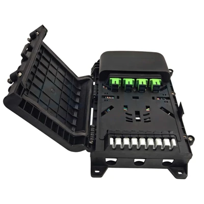
The GFS-8Q combines feeder-cable entry, fiber routing, splitter accommodation and connectorized drop distribution in one enclosure. Eight SC/APC adapter positions serve the subscriber side, while the internal capacity is rated separately at a maximum of 12 fibers.
Network function
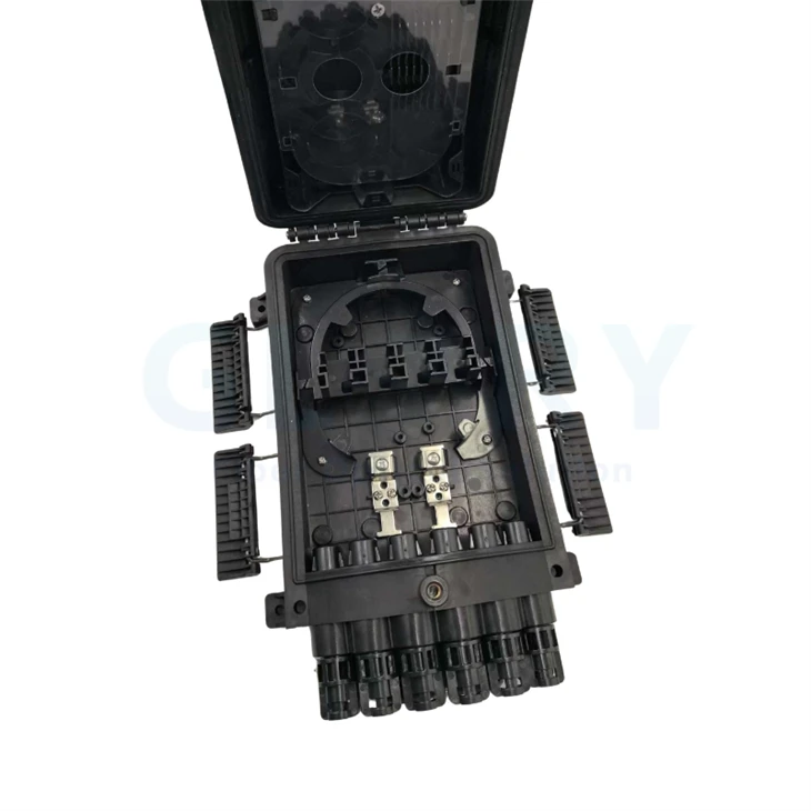
Installed at an FTTH distribution point, the box receives the feeder cable, organizes internal fibers, accommodates a 1×8 micro PLC splitter and presents up to eight SC/APC service interfaces. Compatible output paths include 2×3 mm flat FTTH drop cable and Ø5 mm armored cable.
Enclosure and mounting concept
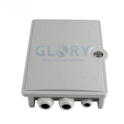
The 280 × 182 × 82 mm IP68 enclosure supports wall, pole and aerial mounting. Fiber-routing features maintain a bend radius above 40 mm, and the installation-center dimensions are 52 × 128 mm and 166 × 186 mm for the illustrated mounting patterns.
Capacity and port count are different
The GFS-8Q has eight SC/APC adapter positions and a maximum capacity of 12 fibers. The eight-port count defines connectorized service positions; the 12-fiber value defines the enclosure's overall fiber capacity. Splitter loading, splicing and adapter population must follow the approved port map.


Key product features
GFS-8Q 8-Port Fiber Termination Box Features
Each feature addresses a separate capacity, optical-interface, cable-routing, environmental or installation decision.
Eight Service Ports with 12-Fiber Capacity
Eight SC/APC adapter positions define the connectorized distribution side, while the enclosure supports a maximum capacity of 12 fibers. Keeping these values separate lets planners assign service ports without treating adapter count as splice or storage capacity.
1×8 Micro PLC Splitter Provision
The internal layout accommodates one 1×8 micro PLC splitter for point-to-multipoint PON distribution. This allows one feeder path to be organized toward eight SC/APC service positions when the loaded splitter, pigtail lengths and port map are specified in the project BOM.
Defined Feeder and Drop Cable Profiles
The feeder entry is specified for a 13 mm cable diameter. Eight optional distribution entries support 2×3 mm FTTH drop cable or Ø5 mm armored cable, giving procurement concrete cable profiles to match instead of ordering by port count alone.
Fiber Routing Above 40 mm Bend Radius
Internal routing controls the fiber bend radius above 40 mm. This provides a defined routing limit for technicians arranging splitter pigtails, feeder fibers and drop fibers, reducing the chance that stored fiber is forced into tight turns during installation or re-entry.
IP68 Outdoor Enclosure Rating
The GFS-8Q carries an IP68 rating for dust and water ingress protection under the applicable rated conditions. For handholes or flood-prone sites, the project should still define cable sealing, assembly procedure, immersion conditions and post-installation inspection.
Wall, Pole or Aerial Mounting
One enclosure can be installed on a wall, fixed to a telecom pole with optional pole rings, or suspended from an aerial support wire with the illustrated overhead hardware. Selecting the mounting kit with the enclosure keeps site hardware aligned with the planned OSP node.
Product configuration
GFS-8Q Standard Configuration and Project Options
The enclosure platform is defined by its dimensions, capacity, protection rating, cable entries and mounting methods. Loaded optical components and project identification should be confirmed separately.

Dimension reference: enclosure 280 × 182 × 82 mm; installation dimensions 52 × 128 mm and 166 × 186 mm.
Technical data
GFS-8Q Fiber Termination Box Technical Specifications
The tables keep fiber capacity, adapter ports, splitter provision and cable compatibility as separate fields for engineering review and purchasing.
General Technical Specifications
Product identity, capacity, protection, dimensions and installation data.
| Item | Specification | Selection Note |
|---|---|---|
| Product model | GFS-8Q | Use the model with the approved image, drawing and project BOM. |
| Product family | Fiber termination box | For FTTH/FTTx feeder-to-drop termination and distribution points. |
| Service port count | 8 | Eight connectorized subscriber-side positions. |
| Adapter capacity | 8 × SC/APC | Confirm whether adapters are supplied loaded or as installation positions. |
| Maximum fiber capacity | 12 fibers | Do not substitute this value for the eight-port adapter count. |
| Splitter provision | 1 × 1×8 micro PLC splitter | Confirm pigtail lengths, connectorization, test criteria and port map. |
| Dimensions | 280 × 182 × 82 mm | A × B × C in the dimensional drawing. |
| Installation dimensions | 52 × 128 mm / 166 × 186 mm | Use the applicable mounting-center pattern shown in the approved drawing. |
| Minimum managed bend radius | More than 40 mm | Applies to fiber routing inside the enclosure. |
| Ingress protection | IP68 | Installation quality still depends on correct cable sealing and enclosure assembly. |
| Mounting methods | Wall, pole or aerial | Match the accessory set to the installation location. |
| Standard accessories | User manual × 1; accessory bag × 1 | Confirm the accessory-bag contents on the approved packing list. |
| Optional accessory | Pole ring × 2 | Specify when pole mounting is required. |
Model and Capacity Table
| Model | Maximum Fiber Capacity | SC/APC Positions | Splitter Provision | Dimensions | IP Rating |
|---|---|---|---|---|---|
| GFS-8Q | 12 fibers | 8 | 1 × 1×8 micro PLC | 280 × 182 × 82 mm | IP68 |
Splitter Configuration
| Splitter Type | Input | Outputs | Adapter Interface | Configuration Status |
|---|---|---|---|---|
| Micro PLC splitter | 1 | 8 | Up to 8 × SC/APC positions | The enclosure can accommodate one 1×8 unit; loaded supply and optical acceptance values are project-defined. |
Optical acceptance boundary
Insertion loss, return loss, operating wavelength, uniformity, polarization-dependent loss and directivity apply to the selected splitter and connectorized assembly, not to the empty enclosure. State these values on the splitter BOM and test plan when ordering a loaded GFS-8Q.
Cable and Connector Compatibility
| Connection Area | Supported Configuration | Project Field to Confirm |
|---|---|---|
| Feeder input | 13 mm cable diameter | Actual cable construction, outside diameter, strength member and sealing components. |
| Distribution outputs | Eight optional cable entries | Number of activated entries and unused-port sealing arrangement. |
| Flat FTTH drop cable | 2 × 3 mm profile | Fiber count, strength-member construction, jacket and termination method. |
| Armored output cable | Ø5 mm profile | Armor construction, cable retention, preparation method and sealing components. |
| Connector interface | SC/APC adapter positions | Adapter loading, pigtail connectorization, boot clearance and dust-cap requirement. |
| Internal fiber routing | Bend radius above 40 mm | Splitter pigtail length, splice plan and fiber-storage route. |
Application scenarios
GFS-8Q Fiber Termination Box Applications and FTTH Solutions
The GFS-8Q fits eight-port access nodes where feeder entry, 1×8 splitting, SC/APC distribution and the mounting environment must be defined together.
8-Port Fiber Termination Box for FTTH Last-Mile Distribution
Choosing an enclosure only by subscriber count can leave the feeder diameter, splitter package and output cable profile unresolved. The GFS-8Q combines a 13 mm feeder entry, one 1×8 micro PLC splitter position and eight SC/APC service positions at the last outdoor distribution point before subscriber drops. It accepts 2×3 mm FTTH drop cable or Ø5 mm armored output cable. Before purchasing, confirm the loaded splitter, pigtail lengths, splice plan, active port count, unused-port sealing, drop-cable construction and optical acceptance values.
Pole-Mounted GPON or XGS-PON Access Node
A generic wall box can require improvised straps or brackets when the survey specifies a pole node. The GFS-8Q supports pole mounting with two optional pole rings while keeping splitter, fiber routing and eight subscriber interfaces inside the IP68 enclosure. Install it on a telecom pole along an FTTH distribution route and connect the 13 mm feeder path to compatible flat or Ø5 mm output cables. Confirm pole diameter, ring size, enclosure orientation, cable slack, grounding needs for armored cable, splitter loading and safe technician access before release.
Aerial OSP Distribution on Support Wire
Attaching a standard wall enclosure directly to an aerial route can leave the support method and drop-cable exit direction undefined. The GFS-8Q includes an illustrated overhead arrangement that suspends the enclosure from the support wire, while internal routing maintains a bend radius above 40 mm. Position it at an aerial FTTH branch point serving up to eight SC/APC drops. Procurement should confirm the suspension hardware, wire dimensions, wind and mechanical design requirements, feeder and output cable profiles, closure orientation, port sealing and installation method.
Wall-Mounted Building or MDU Fiber Distribution
An indoor-only box may not provide the ingress rating or feeder accommodation required at an exposed building entry. The GFS-8Q supplies an IP68 enclosure, 280 × 182 × 82 mm footprint and wall-mounting patterns for a compact FTTH or MDU distribution node. Use it between the incoming feeder and up to eight SC/APC-connected drops routed toward subscriber floors or premises. Confirm wall substrate, fixing hardware, service clearance, cable approach, 1×8 splitter configuration, splice allocation, labeling and whether the site requires additional impact or fire-performance criteria.


Project ordering
GFS-8Q Fiber Termination Box Ordering Configuration
Include these fields in the RFQ so the delivered enclosure matches the approved ODN topology, cable set and installation hardware.
| Ordering Field | GFS-8Q Configuration | Information to State on the RFQ |
|---|---|---|
| Model and quantity | GFS-8Q | Order quantity, approved drawing or sample reference and BOM revision. |
| Capacity | 12 fibers maximum; 8 service ports | Splice allocation, active port count, spare fiber plan and port map. |
| Adapter interface | Up to 8 × SC/APC positions | Loaded or unloaded supply, adapter quantity, dust caps and port numbering. |
| PLC splitter | Space for 1 × 1×8 micro PLC | Loaded or unloaded supply, fiber type, pigtail lengths, connectorization and optical acceptance values. |
| Feeder cable | 13 mm diameter | Cable construction, outside diameter, strength member, retention and entry components. |
| Output cables | 2×3 mm flat or Ø5 mm armored cable | Cable profile, active entry count, sealing components and unused-port treatment. |
| Mounting | Wall, pole or aerial | Required mounting set, pole-ring requirement and site fixing details. |
| Identification | Project-defined | Port labels, product label, logo artwork, lot code and barcode data. |
| Packaging | Project-defined | Unit protection, accessory list, carton marks and packing-list format. |
| Documents and tests | Project-defined | Drawing, packing list, inspection record and optical report for the loaded assembly. |
Recommended RFQ line
GFS-8Q 8-port fiber termination box, 12-fiber maximum capacity, IP68, 280 × 182 × 82 mm, 8 × SC/APC positions, 1 × 1×8 micro PLC provision, 13 mm feeder input, [2×3 mm flat / Ø5 mm armored] outputs, [wall / pole / aerial] mounting, splitter loading [ ], labels [ ], tests [ ] and packaging [ ].
OEM and project support
OEM GFS-8Q Enclosure and Loaded-BOM Control
For repeat FTTH projects, control the enclosure, splitter, adapter set, cables and accessories through one approved drawing and BOM.
Configuration Review
Confirm the 12-fiber capacity, eight service ports, splitter loading, splice allocation and subscriber port map.
Cable-Entry Review
Match the 13 mm feeder input and selected 2×3 mm or Ø5 mm output profiles to the sealing and retention parts.
Loaded Assembly
Define the 1×8 micro PLC splitter, SC/APC adapters, pigtail lengths, fiber type and optical acceptance plan.
Mounting Confirmation
Approve wall, pole or aerial hardware against the site survey and installation drawing.
Label and Packing Control
Provide port numbering, logo artwork, product labels, lot identification, accessory list and carton marks.
Sample-to-Batch Control
Freeze the approved enclosure, internal layout, loaded BOM, test requirements and packing revision before batch production.
Company background
Why Glory Optical for GFS-8Q Project Supply
Glory Optical Communication is a Ningbo-based passive fiber optic infrastructure manufacturer founded in 2008. Its 20,000 m² facility brings R&D, molding, assembly and testing functions together for FTTH, ODN, outdoor plant and OEM/ODM projects.
Enclosure Tooling and Assembly
Mold development and enclosure assembly support control of housing geometry, gasket position, cable-entry details, splice-tray layout, adapter population and internal fiber routing for standard and project-based fiber boxes.
Loaded FTTH Box Integration
Fiber boxes, PLC splitters, adapters, pigtails and cable-management parts can be reviewed as one loaded assembly. For the GFS-8Q, the controlled fields include splitter ratio, SC/APC port map, pigtail length, cable profile and mounting set.
Optical and Assembly Checks
Connectorized products can be checked for insertion loss, return loss and connector end-face condition where applicable. Enclosure orders can also be checked against the approved specification, drawing, port map and packing requirement.
OEM / ODM Project Workflow
Project support can cover drawing or photo review, specification confirmation, sample planning, testing, labels, packaging and batch supply. This keeps the enclosure and loaded optical BOM aligned through repeat orders.
Build an orderable eight-port FTTH node
Specify the GFS-8Q Around the Actual Cable and Splitter BOM
Send the feeder cable diameter, output cable profile, 1×8 splitter configuration, SC/APC port map, splice allocation, mounting method, labels, test requirements and packaging instructions. Glory Optical can review the complete GFS-8Q configuration before quotation.

Our Quality Promise
Comprehensive 3-Year Warranty
We confidently back all our products with a 3-year warranty. Our specific service policy is: within one year for quality issues, we take full responsibility for returns; within two years, for replacements; and within three years, for repairs.
Clear & Competitive MOQ
We welcome both trial and bulk orders. Our standard Minimum Order Quantity (MOQ) is 50 units. We also offer free samples for testing to help you evaluate our quality with confidence.
Fast & Reliable Logistics
We guarantee delivery within 10 days for standard items. Our logistics advantage includes cost-effective door-to-door service to simplify shipping for you.
Our Foundation
Backed by 18 years of experience since 2008, we control quality from our own factory, accept OEM/ODM requests, and maintain ready stock for wholesale. We focus on delivering the optimal balance of price and quality directly to end customers worldwide.
Your trust is our priority. Partner with us for dependable fiber optic solutions supported by clear promises.
Hot Tags: ip68 8-port fiber termination box, China ip68 8-port fiber termination box manufacturers, suppliers, factory, Fiber Access Terminal Box, fiber breakout box, fiber outlet box, Fiber Termination Enclosure, Mst Box, outdoor fiber distribution box