The patch panel is the most frequently touched passive component in any fiber network. Over the operational life of a data center or FTTH distribution node, technicians connect, disconnect, clean, label, and reroute patch cords at these panels hundreds of times. Every design decision you make at installation - density, form factor, MPO type, cassette vs. fixed, labeling system - compounds over every one of those touches.
This article does not describe patch panels in general. It describes the specific failure modes that emerge in real deployments, why they are predictable from the original design decision, and what engineering constraints govern the tradeoffs. The two deployment contexts we examine are the data center spine-leaf fabric at 400–1000 port density, and the FTTH ODF at a 5,000-subscriber distribution node - because they represent opposite extremes of the same problem: managing fiber connections at scale, in environments where maintenance resources are constrained.
The Density Decision: Why You Cannot Simply "Go Higher"
The fiber networking industry has trended toward higher port density for 20 years. 1U panels moved from 12 ports to 24 to 48 to 96 LC duplex. High-density MPO cassette frames now achieve 144 to 288 LC equivalent connections in 1U. The marketing pitch is straightforward: more ports per rack unit reduces footprint, reduces total rack space, reduces cost per port.
What this pitch omits is the operational consequence. In a 48-port 1U LC duplex panel, each connector is accessible with a straight, direct hand motion. A technician locates the port, cleans the ferrule, inserts the cord, and moves on. In a 96-port or 144-port ultra-high-density panel, the physical geometry changes: ports are closer together, some require angled connectors or tool-assisted access, and pulling one cord in a fully populated panel moves neighboring cords. The real cost of high-density panels is not the panel itself. It is the labor per port-touch over the panel's operating life.
Panels rated above 48 LC duplex per 1U (i.e., >2.0 ports/cm of panel width) almost universally require some form of angled or push-pull LC connector to achieve clean access in a fully populated state. Angled connectors increase per-connector cost by 30–60% and create labeling complications that compound over time. Factor this into total cost of ownership before committing to ultra-high-density during initial procurement.
There is also an airflow consideration that is frequently absent from patch panel procurement discussions. Fiber optic panels themselves generate no heat, but in high-density environments, cable bundles behind panels create resistance to airflow. A fully populated 2U high-density panel with 144 ports can accumulate a cable bundle depth of 80–120mm at the rear, which, in a front-to-back airflow architecture, creates significant airflow obstruction for the equipment in adjacent rack positions.
The correct engineering frame is: what density is appropriate for this specific rack position, given the expected operational cadence (how often will individual ports be moved), the cable management depth available, and the cleaning access constraints of the environment? Ultra-high density is the right answer for passive top-of-rack pre-terminated trunk terminations that are touched once. It is the wrong answer for active-zone panels with frequent MACs (moves, adds, changes).
Cassette-Based Systems: The Flexibility That Creates New Failure Points
Cassette-based (or "modular") patch panel systems have become standard in high-density data center deployments. The architecture is simple: a 1U or 2U chassis accepts interchangeable cassette modules, each containing a pre-terminated fiber array - typically 12 LC duplex ports on the front and an MPO-12 or MPO-24 connector on the rear that accepts a pre-terminated MPO trunk cable.
The installation advantage is real. A rack of cassette-based panels can be fully commissioned in a fraction of the time required for spliced or field-terminated solutions. MPO trunk cables connect the cassette rear to the remote end - typically another cassette, a fiber distribution frame, or a transceiver - with no field splicing, no connectorization, and no OTDR testing of individual fibers during installation.
The failure mode is also real, and it emerges from the same structural characteristic that creates the installation advantage.
The Contamination Accumulation Problem
Each cassette module introduces two additional connection points relative to a direct-connect solution: the MPO-to-MPO connection at the rear of the chassis, and the internal routing from the MPO array to the LC ports on the front face. In a typical data center link, the path might be:
Each connector interface is a contamination risk. IEC 61300-3-35 defines the pass/fail threshold for connector end-face contamination at 0.2 dB additional insertion loss for single-mode, but contamination rarely causes a clean step failure - it accumulates gradually, as particulates adhere to the ferrule end face during partial insertions, accidental non-mated exposure, and inadequate cleaning technique. In a cassette system, the rear MPO connectors are typically inaccessible without removing the cassette from the chassis. These connectors are almost never cleaned in operational environments because the cleaning procedure requires partial disassembly of the panel assembly and is not included in standard first-responder troubleshooting protocols.
In high-MAC environments, the most common unexplained intermittent link degradation (link flapping, BER increases, transceiver Rx power drop) in cassette-based panels is rear MPO connector contamination - not the visible front LC connections that technicians clean. Because these connectors are not visible and are not included in standard work instructions, they are typically not investigated until all other causes have been ruled out. Mean time to identify this failure mode in the field: 4–8 hours of troubleshooting per affected link.
- Installation time: 60–80% faster than field-terminated
- No OTDR per-fiber testing at install
- Modular reconfiguration: swap cassette type without re-cabling trunk
- Factory-tested IL/RL on every cassette - consistent performance
- Supports both B2B and Method B MPO polarity in same chassis
- 8 connector interfaces per link vs. 4 (doubles contamination risk)
- Rear MPO connectors inaccessible without partial disassembly
- Higher per-port IL: cassette typically adds 0.35–0.55 dB vs. fixed panel
- Polarity error at rear MPO multiplied across all 12 front LC ports
- Higher upfront cost: chassis + cassette + MPO trunk vs. panel + patch cord
MPO Polarity: The Failure That Scales With Your Deployment
MPO polarity is the single most documented source of deployment failure in pre-terminated fiber systems, and it remains poorly understood in the field. The core issue: an MPO connector contains 12 or 24 fibers arranged in a linear array. The transmit fiber at position 1 on one end of a link must terminate at the receive port at position 1 (or the corresponding mapped position) at the other end. If the polarity method is not consistently applied across the entire link - trunk cables, cassettes, cassette orientation within the chassis - the result is either an Rx-to-Rx connection (no signal) or a cross-connected parallel channel assignment.
TIA-568.3-D defines three polarity methods: Method A, Method B, and Method C. IEC 61754-7-1 provides the physical MPO connector specification. The critical constraint that operators routinely underestimate: polarity method is not a property of a single component. It is a property of the entire link system. A Method B trunk cable combined with a Method A cassette at one end and a Method B cassette at the other produces incorrect polarity on every fiber pair. This error cannot be corrected by replacing the cassette - it requires a systematic re-analysis of the complete link path.
The operationally significant consequence: in a 400-port MPO deployment with mixed polarity methods, identifying and correcting polarity errors requires systematic tracing of each individual link - a process that, at typical field technician productivity, requires 8–15 minutes per link. A 20% error rate across 400 links yields 80 links × 12 minutes = approximately 16 person-hours of purely corrective labor, consuming no productive output.
Prevention is straightforward but requires upfront system design discipline: define the polarity method at the beginning of the project, document it in the cabling records, specify it on purchase orders for every component (trunks, cassettes, adapter plates), and verify polarity before the panel is populated. Most operators who have managed a large MPO polarity remediation project implement a mandatory "polarity matrix" review as a formal gate in their commissioning checklist.
When sourcing components from multiple vendors for an MPO system, obtain written confirmation of the polarity method used in each component type. Do not assume consistency across brands or even across product generations from the same brand. When Glory Optical supplies MPO trunk cables and cassettes as a system, all components are factory-specified to a single declared polarity method and labeled accordingly.
Loss Budget Accumulation: Why Your Link Works at Commissioning and Fails at Year 3
Optical power budgeting is performed at link design stage. For a typical 100G SR4 multimode link using OM4 fiber, the available loss budget is 3.0 dB (IEEE 802.3bm). For a 10G LR single-mode link over OS2, the budget is significantly larger - 10.0 dB (IEEE 802.3ae) - which creates a false sense of margin in long-term planning.
The problem is that loss accumulates over time through mechanisms that are invisible at commissioning:
Contamination accumulation. A clean LC connector on OM4 fiber contributes approximately 0.1–0.2 dB insertion loss at commissioning. After 12–18 months of operation in a data center environment (dust, positive air pressure, periodic partial unmating), contamination can raise this to 0.4–0.8 dB. Across a 4-connector link, this represents 0.8–2.4 dB of additional loss - potentially exceeding the entire margin for a short-reach multimode link.
Connector wear. IEC 61754-4 specifies LC connector mechanical durability at 500 mating cycles minimum. High-turnover ports in active patch areas may approach this limit within 3–5 years of operation. Wear increases insertion loss and return loss degradation simultaneously.
Bend radius violations. Patch cord management in high-density panels frequently produces bend radii below the IEC 61300-3-1 minimum (typically 30mm for standard single-mode, 7.5mm for G.657A2 bend-insensitive). A single bend radius violation on OS2 fiber can contribute 0.3–1.0 dB of additional loss depending on severity and wavelength. Because the violation is in the installed cable path rather than a connector, it is not identified by standard cleaning and reseating troubleshooting.
The engineering implication: initial loss budget calculations must include a degradation reserve - a minimum of 0.5–1.0 dB held in reserve for expected 3-year contamination accumulation. For multimode links with tight budgets (3.0 dB total), this reserve is not always available without reducing link reach. For single-mode links with generous budgets (10 dB+), the reserve is available but is rarely formally allocated, resulting in perceived "unexplained" link failures in years 4–6 that are actually the predictable result of ignoring long-term loss accumulation.
Cable Management Behind the Panel: Where Installations Fail Operationally
The physical management of patch cords behind a fiber panel is the operational consideration most frequently neglected during system design, and the one most likely to cause ongoing maintenance problems. In a data center environment, this is a real constraint: a fully populated 2U patch panel may have 144 LC duplex connections, each with a patch cord exiting the rear. Properly routing and managing 144 individual patch cords in a 1-2U space, while maintaining minimum bend radius, accessible labeling, and the ability to trace and replace any individual cord without disturbing its neighbors, is a mechanical engineering problem.
Common failure patterns observed in the field:
Cord bunching at entry angles. When patch cords exit the rear of a panel in a bundle and are then routed through a cable management arm or horizontal manager, the outermost cords in the bundle bend more sharply than the inner cords. In a 144-port panel, the outer cords in a 15-cord bundle may reach bend radii of 15–20mm - below the 30mm minimum for standard OS2 single-mode. The inner cords are correctly routed; the outer ones are in chronic bend violation. Since there is no easily visible indicator of this violation, it persists indefinitely.
Label obscuration. Cable labels applied at the patch cord's panel end are obscured by the cable bundle within weeks of the panel being fully populated. This forces technicians to trace individual cords by following them to their other end - a time-consuming process that itself risks disturbing adjacent cords. In high-MAC environments, this results in incorrect cord identification and consequent mis-disconnection, which may cause service outages.
Panel strain accumulation. Patch cords that are not supported within 150mm of their panel connector (per TIA-569-D recommendations for fiber cabling support intervals) create continuous lateral strain on the LC or SC connector body. Over time, this degrades the mating contact between the connector ferrule and the panel adapter, increasing insertion loss. This is particularly problematic for horizontal panels where gravity acts perpendicular to the connector axis.
Plan for a minimum 150mm of cable management depth behind any panel with more than 48 ports, and 200mm for panels above 96 ports. Use 1U horizontal cable managers (radius-limiting type, not plain D-rings) between every populated panel. For vertical cable management, use a cable trough with radius-limiting guides at entry and exit points. Do not use tie wraps on fiber patch cord bundles - use hook-and-loop straps at a maximum tension of 0.1 N·m (finger-tight).
The FTTH ODF Context: Different Scale, Same Failure Modes
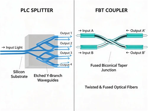
The fiber distribution frame (FDF) or optical distribution frame (ODF) in a FTTH ODN environment is structurally analogous to a data center patch panel, but the scale and operational constraints differ significantly. At a 5,000-subscriber distribution node, a central office ODF may terminate 500–2,000 fibers from the feeder layer, route through multiple PLC splitters (typically 1:32 or 1:64 in a two-stage split architecture), and distribute to individual subscriber drop circuits.
The critical operational difference from the data center context: FTTH ODFs are accessed infrequently for individual subscribers but intensively during fault conditions - when a splice closure fails, or a distribution cable is damaged, multiple subscriber services are affected simultaneously, and the ODF becomes the convergence point for repair activity. In this environment, connector contamination and labeling failures have a direct relationship to mean time to repair (MTTR) for subscriber service restoration.
The operational challenge in a FTTH ODF is that the loss budget is consumed primarily by the PLC splitter stages (~10.5 dB for 1:8 per stage). The ODF connector contribution, while appearing small (0.5–1.0 dB total at commissioning), consumes a disproportionate share of the available margin, because the splitter loss is fixed and cannot be reduced. Any contamination-induced increase at the ODF level directly subtracts from subscriber receive power margin.
This makes FTTH ODF connector maintenance more operationally critical than in most data center applications - a single contaminated SC/APC connector at the ODF may degrade 8 to 64 subscriber services simultaneously, depending on the split ratio stage at which it occurs.
LC Duplex vs. MPO: The Migration Decision You Cannot Reverse
In data center environments, the transition from 10G to 100G, and the anticipated transition to 400G, has forced a structural question that organizations frequently defer: when should the patch panel infrastructure commit to an MPO backbone?
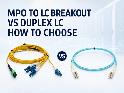
The question is not simply about current bandwidth. MPO-based infrastructure, once installed as the backbone, is more difficult to extend using standard single-fiber LC-based connectivity because it requires either LC breakout cassettes (which add connector count and the associated contamination risk described in Section 02) or full MPO connectorization at both ends of every link. Conversely, an LC duplex backbone, extended to support 100G or 400G parallel optics, requires either:
- → Parallel single-mode breakout cables (8-fiber or 4-fiber bundles per 100G or 25G lane) - achieves the parallel structure without MPO, but at high per-port cost and extreme cable management complexity at scale.
- → Full migration to MPO backbone - requires recabling or overlaying a parallel MPO infrastructure, which at 400+ port scale involves substantial capital and labor cost, and an operational period where both infrastructures coexist, increasing complexity.
- → BiDi (bidirectional) optics on single-fiber LC - achieves 40G or 100G on two fibers using dual-wavelength CWDM, avoiding the parallel fiber requirement entirely. The limitation is transceiver cost (BiDi QSFP28 at approximately 2–3× standard SR4) and vendor lock-in on optic selection.
The practical engineering guidance: organizations planning infrastructure that will need to support 400G within 3–5 years should provision MPO-ready patch panels (chassis-based, cassette-compatible) even if initial population uses LC duplex cassettes. The chassis represents a minor upfront cost premium but preserves the ability to swap to MPO cassettes without recabling the backbone trunks.
| Factor | LC Duplex Panel | MPO Cassette Panel | Assessment |
|---|---|---|---|
| Initial port cost | Lower | Higher (+20–40%) | LC WINS |
| 400G readiness | Requires recabling backbone | Swap cassette type only | MPO WINS |
| Connector count per link | 4 interfaces | 8 interfaces | LC WINS |
| Installation speed | Standard (field termination or patching) | Fast (pre-terminated trunks) | MPO WINS |
| Loss budget per link | Lower total (4 connectors) | Higher (0.3–0.5 dB MPO overhead) | LC WINS |
| Parallel 100G/400G support | Requires BiDi or breakout bundle | Native 8-fiber/4-fiber parallel | MPO WINS |
| Polarity error risk | Minimal (individual fiber) | Significant (12/24 fibers affected) | LC WINS |
| Maintenance access (rear) | Direct LC access, easy cleaning | MPO rear access requires partial disassembly | LC WINS |
The table does not produce a clear winner - which is accurate. The decision is context-dependent, and the dominant variable is the expected migration timeline to parallel optics. If 400G deployment is planned within 3 years, the MPO infrastructure cost is justified. If 400G is a 7–10 year horizon, the LC duplex approach with BiDi optics at the transceiver layer may be lower total cost.
Labeling Systems That Fail at Scale
Fiber patch panel labeling is treated as a peripheral concern during design and a critical operational problem at year 2. The failure modes are consistent across deployment types:
Adhesive label degradation. Standard adhesive labels applied to patch cord jackets degrade in data center environments due to heat, vibration, and repeated contact during cord management. In a 3-year operational period, 30–50% of adhesive labels in a high-activity patch area will show reduced legibility, with 10–20% becoming entirely unreadable. This creates a labeling maintenance burden that is rarely resourced in operational budgets.
Naming convention drift. In environments managed by multiple technicians over multi-year periods, without a rigorous documented naming convention, label text diverges from the convention over time. Port A-1-24 becomes "switch-3-port-24" becomes "sw3p24" becomes "sw3-24" as different technicians apply their own shorthand. Cross-referencing labels to network documentation becomes unreliable.
High-density label occlusion. At 96 or more ports per 1U, individual port labels on the panel face are physically too small for reliable reading without optical magnification in the typical data center lighting environment. This problem has no solution at ultra-high density - it is a physical constraint of the form factor.
Operationally robust labeling for patch panels requires: printed heat-shrink or clip-on labels on both ends of every patch cord (not adhesive), a documented and enforced naming convention captured in network management records, and panel-level diagrams (physical or digital) showing port assignments. For deployments above 200 ports, a dedicated cable management database (such as NetBox or similar DCIM tools) synchronized to physical installation records significantly reduces fault isolation time.
Procurement Engineering: What to Specify That Most Buyers Don't
Standard patch panel procurement specifications typically address: port count, port type (LC/SC/MPO), fiber type (OS2/OM4), and panel form factor (1U/2U). These parameters are necessary but insufficient. The following specifications are frequently omitted from purchase orders and subsequently become sources of performance or operational problems:
Engineering Summary: The Decisions That Define Long-Term Performance
Fiber patch panels are passive components with no intrinsic moving parts. Their failure modes are entirely determined by design decisions made before installation, and by the maintenance protocols implemented after installation. The decisions that create maintenance debt are predictable:
Choosing ultra-high-density panels for high-MAC zones creates per-port labor costs that erode the capital cost savings within 18–24 months. Deploying cassette systems without accounting for rear MPO connector accessibility creates a contamination accumulation mode that is structurally inaccessible to standard cleaning maintenance. Ignoring polarity method at system design creates errors that scale linearly with port count. Commissioning links without a formal loss budget degradation reserve guarantees unexplained failures in years 3–5.
None of these failure modes require extraordinary events. They are the normal operational consequence of normal engineering decisions made without accounting for operational reality.
The correct approach is to design the patch panel system from the operational end backward: define the expected MAC cadence, define the cleaning access requirements, define the polarity method as a system-wide attribute, specify a loss budget that includes a degradation reserve, and procure components - panels, cassettes, trunks, adapters - as a coherent system with documented performance specifications rather than as individual line items optimized on unit price.
Glory Optical supplies high-density fiber patch panels, MPO/MTP cassette systems, OS2 and OM4/OM5 pre-terminated trunk cables, and ODF frames as configured systems. All cassette products ship with per-port IL/RL test reports. Polarity method is documented on every MPO product. Custom panel configurations, cassette type mixtures, and OEM labeling are available. Free samples for qualified evaluation projects; 2-hour quote response.
→ Data Center Cabling Product Range · Request Engineering Consultation
Standards and Specifications Referenced
IEC 61754-4: Fiber optic connector interfaces - Type LC connector family. Defines LC mechanical interface geometry and mating durability requirements.
IEC 61754-7-1: Fiber optic connector interfaces - Type MPO connector family. Defines MPO physical specifications including key orientation and fiber array geometry.
IEC 61300-3-4: Fiber optic interconnecting devices - measuring instrument of insertion loss and return loss. Defines measurement methodology for connector optical performance.
IEC 61300-3-35: Examination and measurement of fiber optic connectors - visual and automated inspection. Defines contamination classification for connector end-face inspection.
TIA-568.3-D: Optical Fiber Cabling Components Standard. Defines polarity methods (A/B/C) for MPO-based cabling systems.
TIA-569-D: Telecommunications Pathways and Spaces. Defines minimum bend radius and support interval requirements for fiber cabling in structured installations.
IEC 60529 (IP Code): Degrees of protection provided by enclosures. Relevant for FTTH ODF installations in outdoor-adjacent or OSP environments.
IEEE 802.3bm: 40Gb/s and 100Gb/s fiber optic task force. Defines optical power budget parameters for 100GBASE-SR4 OM4 multimode links.