In an outside plant (OSP) network, the fiber cable itself is rarely the first thing to fail. Far more often, trouble starts where the fiber is joined, terminated, sealed, or handled - at connection points that sit outdoors through rain, heat, UV, vibration, and repeated maintenance. Understanding why those points fail is the difference between chasing intermittent faults for years and building a link that stays inside its loss budget.
This guide breaks down the seven OSP problems that quietly raise optical loss and drive up maintenance cost. For each one it follows the same practical chain: why it happens → what it looks like in the field → how to test for it → how to fix it with the right product or design → and what evidence to capture at acceptance.
Quick Answer: OSP Fiber Failures Usually Start at Connection Points
The short answer for network planners
In many OSP fault investigations, failures do not start in the middle of a buried or aerial cable. When a link develops unexplained loss, the high-risk locations are almost always connection and access points, not the cable span:
- splice closures
- fiber distribution boxes (FDB)
- MST / NAP terminals
- hardened connectors
- drop ports
- field splices
- poorly sealed unused ports
When an outdoor link shows unexplained loss, the first inspection points should usually be the connector, splice tray, cable entry, unused port seal, and bend radius - not the middle of the buried cable.
The failure-to-cost chain
The reason these problems deserve attention is that each one triggers the same expensive sequence:
Poor sealing / contamination / splice loss / bend stress
        ↓
Higher insertion loss or intermittent link
        ↓
OTDR troubleshooting and site visit (truck roll)
        ↓
Closure reopening, rework and customer outage
        ↓
Higher OSP maintenance cost
Over time, a single degraded connection point can often cost more to investigate and rework than the price difference of a hardened, sealed, and properly tested product that would have prevented it.

Why Fiber Connectivity Matters More in Outside Plant Networks
OSP networks have more uncontrolled variables than indoor cabling
Indoor structured cabling lives in a controlled environment: stable temperature, no rain, low vibration, and technicians who rarely reopen a panel. OSP is the opposite. The same link may pass through underground ducts, direct-buried sections, aerial spans, handholes, pedestals, poles, and roadside cabinets - each with its own exposure to temperature swings, rain, UV, wind-induced vibration, insects, rodents, and accidental damage from third-party digging.
Because of that, OSP connection products cannot be judged on optical performance alone. Sealing, mechanical protection, cable routing, labeling, and testability matter just as much as insertion loss, and they are what separate a link that survives ten years outdoors from one that starts drifting after the first wet season.
More connection points mean more failure points
Every point where the fiber is opened, joined, or terminated is a potential source of loss. The table below maps common OSP locations to their typical connection risk:
| OSP Location | Typical Connection Risk |
|---|---|
| Splice closure | water ingress, splice tray pressure, sealing aging |
| FDB / NAP | connector contamination, port labeling error |
| MST terminal | unused port sealing, hardened connector mismatch |
| Handhole | standing water, crushed cable, mud contamination |
| Pole / aerial route | vibration, wind load, bird / rodent damage |
| FTTA site | tight routing, jumper stress, bird pecking |

Problem 1: Water Ingress and Poor Sealing
Why it happens
In many OSP deployments, water is one of the most damaging environmental factors. It rarely gets in through a design flaw in a good enclosure; it gets in through the way the enclosure is installed and maintained. Common causes include a cable gland that was not compressed evenly, a gasket that has aged and hardened, unused ports left open, handholes that flood on a cycle, a closure reopened for service and re-sealed carelessly, or indoor-grade fittings used where outdoor-rated parts belong.
A closure can leave the factory with a good sealing design and still fail in the field if the cable gland is not tightened evenly, unused ports are not capped, or the enclosure is reopened without checking the gasket before closing.
Field symptoms
Water damage usually announces itself indirectly: loss that rises after rain, ports that go intermittent, corrosion on metal parts, a damp splice tray, contaminated connector ferrules, or visible mud and water marks inside the enclosure.
Practical fixes
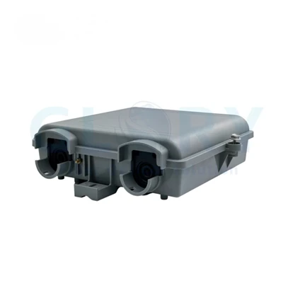
Specify enclosures rated to a defined ingress standard (IEC 60529 IP rating; Telcordia GR-771 for splice closures), use sealed cable glands, fit captive dust caps, and seal every unused port - an open port is a leak path. Handhole deployments deserve extra attention to submersion risk. Before closing any enclosure, photograph the gasket, gland compression, and unused-port seals so their condition is on record.
Acceptance evidence to request
- IP test basis / supplier evidence
- sealing inspection photo
- gland compression photo
- unused-port sealing photo
- pre-shipment packing photo
Problem 2: Connector Contamination and End-Face Damage
Why small dust causes big loss
OSP ports are opened, re-mated, and exposed to dust, grit, and moisture far more than indoor connectors. A single particle trapped between two ferrule end-faces can raise insertion loss, create reflection, and turn a stable link intermittent - and because the fibers are pressed together, a hard particle can leave a permanent scratch that degrades return loss. End-face condition should be judged against a repeatable standard rather than by eye; IEC 61300-3-35 defines pass/fail zones and defect limits for exactly this purpose.
Where contamination usually appears
The recurring hot spots are hardened connectors, SC/APC adapters, splitter output ports, MST drop ports, the patching area inside an FDB, any temporarily opened port, and - often overlooked - the point where a technician performed rework.
Practical fixes
Treat inspect-before-connect and clean-before-connect as mandatory, not optional. Keep dust caps on until the moment of mating, seal unused adapters, and fold the end-face inspection result into the acceptance file. Field cleaning is not a step to skip when time is short - it is usually cheaper than the return visit it prevents.

Suggested checklist
| Item | Field Check |
|---|---|
| Connector cap present | Yes / No |
| End-face inspected | Pass / Fail |
| Cleaning performed | Yes / No |
| IEC 61300-3-35 reference | Included / Not included |
| IL/RL report | Attached / Missing |
Problem 3: Splice Loss and Poor Splice Protection
Why splice loss accumulates in OSP links
A single fusion splice may add only a small fraction of a dB, which looks harmless in isolation. OSP links, however, chain many nodes together, and those small numbers add up. Poor core alignment, weak heat-shrink protection, and sloppy bare-fiber management inside the tray each add loss and, worse, create latent points that drift over time as the enclosure heats, cools, and gets reopened.
Field symptoms
Typical signs are an abnormal loss reading at one OTDR event, insufficient power margin after a splitter, an intermittent ONT at the far end, or inconsistent behavior between branches that share the same closure.
Practical fixes
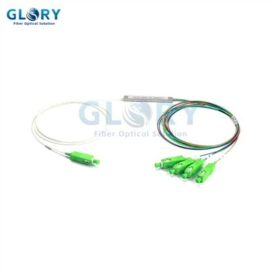
Standardize the fusion process, record an OTDR event value for each splice, and control the bend radius of bare fiber inside the tray. Never let stored cable slack press on a splice sleeve. Every closure should ship with - or be handed over with - a port map and fiber map so future technicians can trace the sequence without guesswork. Where the PON power budget is tight, the splitter itself is part of the loss equation.
Acceptance evidence
- splice loss record
- OTDR trace
- splice tray photo
- closure internal photo
- fiber sequence / port map
Problem 4: Bend Loss From Cable Routing and Mechanical Stress
How bend loss appears outdoors
Bend loss is a workmanship problem as much as a product problem. It comes from a radius that is too tight, an over-tightened cable tie, a cabinet door pinching a jumper, stored slack crushed inside a handhole, wind-induced movement on an aerial route, a drop cable that gets tugged, or an FTTA jumper under stress on a tower.
Microbend vs macrobend
A macrobend is a visible, sharp bend - the kind you can see and correct. A microbend is a small deformation caused by localized pressure, crushing, or jacket stress, often invisible to the eye. Microbends are the more dangerous of the two because they show up as gradual loss drift rather than an obvious fault, and they are easy to miss during a walk-through inspection.
Practical fixes
Define and enforce a minimum bend radius, and use G.657 bend-insensitive fiber (G.657.A1 is common for drop cable) where tight routing is unavoidable. Manage slack deliberately inside handholes and pedestals rather than coiling it wherever it fits, protect FTTA jumpers from stress, and use an armored patch cord on high-stress or exposed paths.

Problem 5: Aging Closures, Gaskets and Outdoor Materials
Aging is not only about the cable
When people plan for OSP lifespan, they think about the cable jacket. But the parts that age fastest are usually at the connection points: the closure shell, the gasket, the cable gland, dust caps, adapters, labels, metal clamps, and the sealing gel or rubber that keeps water out. A closure is only as durable as its shortest-lived sealing part.
Field symptoms
Aging shows up as faded labels, a gasket gone hard, a missing port cap, a cracked housing, a loosened cable entry, contamination in the connector area, and corrosion.
Practical fixes
Specify UV-resistant materials, favor enclosures with replaceable sealing parts, run periodic inspections, and keep a spare cap and gland kit on hand. Build a site photo archive so change is visible over time, and adjust inspection intervals to the environment - coastal, industrial, desert, tropical, and cold climates each age hardware at a different rate.
Maintenance note
Aging cannot be eliminated, but it can be made visible earlier through inspection intervals, labeling records, and replacement planning.
Problem 6: Missing Labels, Port Maps and As-Built Documentation
Why documentation is a connectivity issue, not paperwork
It is tempting to file documentation under "admin," but in OSP it is a direct cause of connectivity failures. Unclear records lead to the wrong fiber being unplugged, technicians who cannot confirm which port they are working on, longer fault-location times, boxes that get reopened repeatedly during FTTH expansion, and - in the worst case - the wrong subscriber being disconnected because the port map was wrong. This is one of the clearest places where disciplined work separates a reliable operator from a reactive one.
An OTDR trace without a port map is only half useful. The technician may know where an event appears on the trace but still lose time identifying which closure, tray, fiber, or drop port the event belongs to.
Minimum documentation package
At a minimum, every connection point should carry: cable route ID, closure ID, tray number, fiber count, port number, splitter ratio, customer / drop ID, OTDR file name, IL/RL record, and before/after site photos.
Why each record matters
| Document | Why It Matters |
|---|---|
| Port map | Prevents wrong disconnect |
| Fiber map | Speeds splice troubleshooting |
| OTDR trace | Baseline for future faults |
| Label photo | Confirms field marking |
| Closure internal photo | Helps future reopening |
| Packing / batch photo | Supports product traceability |
Problem 7: Incomplete Testing Before Handover
"It passed visually" is not enough
A link that looks fine can still be out of budget. Proper OSP acceptance testing covers continuity, polarity, insertion loss, return loss, OTDR, connector end-face inspection, and port map verification - a set aligned with the optical fiber cabling and testing practices in the ANSI/TIA-568.3 series and FOA testing references. Skipping any of these leaves a category of fault undetected until it becomes an outage.
Which test finds which problem
| Test | Finds |
|---|---|
| VFL continuity | wrong routing / broken fiber |
| IL test | total link loss |
| RL test | reflection issue |
| OTDR | splice event, bend event, distance to fault |
| End-face inspection | dust, scratch, defect |
| Port map check | labeling / routing error |
Practical fixes
Deliver the test files with the shipment or as part of project handover, and establish a baseline. Future restoration work depends on that baseline OTDR trace - without it, every fault investigation starts from zero. On high-value OSP projects, do not save only a pass/fail summary; keep the traces and the port-to-fiber correspondence together, because that pairing is what makes the data usable years later.
OSP Fiber Acceptance Checklist
Use this as a go/no-go list before any enclosure is closed and handed over.
Pre-closing inspection
- gasket in place
- cable gland tightened evenly
- unused ports sealed
- bend radius maintained
- tray not overloaded
- no sharp pressure point on fiber
- dust caps installed
Optical test package
- IL / RL
- OTDR
- VFL
- end-face inspection
- polarity
- port map
Handover records
- port map
- fiber map
- closure photo
- label photo
- route ID
- batch label
- repair contact
- spare parts list
Every time an outdoor closure or FDB is reopened, the sealing surface, dust caps, fiber routing, and label condition should be checked again before the box is closed. Maintenance is not only repair; it is a second acceptance event.
Product Selection Guide: Closure, FDB, MST, Drop Cable and FTTA Patch Cord
The right hardware depends on which risk dominates at a given point in the network.
Use a splice closure when the main risk is splice protection
At buried and aerial splice points, the priority is protecting fusion splices and keeping water out. Choose a Fiber Optic Splice Closure - dome or inline, aerial or underground - sized for the required sealing performance and splice tray capacity.
Use an FDB / NAP when the main risk is subscriber access management
Where fibers are distributed to subscribers, the challenges shift to port management and clean patching. A Fiber Distribution Box or NAP with organized splitter outputs, adapter protection, clear port labeling, and proper slack storage keeps that access point maintainable.
Use an MST when plug-and-play drop activation matters
For fast, repeatable FTTH drop activation, an MST with hardened connectors and factory-sealed unused ports removes field splicing from the drop and shortens activation time. Pre-connectorized assemblies keep quality consistent across a large rollout.
Use an armored or FTTA patch cord when the route is exposed
On towers, antenna runs, rodent- or bird-prone routes, and any high-pull-stress path, mechanical protection wins. Choose an FTTA Patch Cord for tower and RRH/BBU connections, and an Armored Fiber Patch Cord with G.657.A1 bend-insensitive fiber where the cable is exposed or at risk of being chewed or crushed.
Product mapping table
| Field Condition | Product Direction |
|---|---|
| Buried or aerial splice point | Splice closure |
| Subscriber distribution point | FDB / NAP |
| Plug-and-play FTTH drops | MST / hardened terminal |
| Tower / RRH / BBU connection | FTTA patch cord |
| Exposed or rodent-prone route | Armored fiber patch cord |
| Tight drop routing | G.657 bend-insensitive FTTH cable |
Field Observations From Public Engineering Communities
These observations are drawn from public field discussions and should be treated as qualitative maintenance signals, not statistical survey results.
Observation 1 - Outdoor failures are often intermittent before they become outages
In many OSP maintenance cases, the first symptom is not a complete fiber cut. It is loss drift: a link that passes acceptance but becomes unstable after rain, temperature change, vibration, or repeated closure opening. The usual culprits are water ingress, connector contamination, a microbend, a loose port, or a compromised seal - problems that intermittently degrade a connection long before they sever it.
Observation 2 - Documentation quality changes repair time
When a port map is missing, a technician has to open the box, trace fibers, and re-test just to establish what should already be known. With a good OTDR baseline and an accurate port map, the same fault is located far faster. The effect is consistent enough to plan around, even without attaching a specific percentage to it.
Observation 3 - OTDR traces are valuable only if someone can interpret them
Field communities discuss OTDR traces constantly, and the recurring lesson is that having the file is not the same as having the answer. A trace becomes useful only when it is paired with an explanation of each event, the port-to-fiber correspondence, and a historical baseline to compare against.
FAQ
Q: What are the most common causes of OSP fiber failure?
A: The recurring causes are water ingress, connector contamination, splice loss, bend loss, physical damage, material aging, and poor documentation - and most of them appear at connection points rather than in the cable span.
Q: How do you test an OSP fiber link?
A: A complete test covers continuity (VFL), insertion loss and return loss (IL/RL), OTDR, connector end-face inspection, and port map verification. Together these confirm the link is both within budget and correctly documented.
Q: What causes high insertion loss in outdoor fiber networks?
A: Common causes are a dirty connector, a bad splice, a bend that is too tight, a damaged cable, a wet closure, or simply too many connectors in the path. End-face inspection and OTDR usually isolate which one.
Q: Why do fiber connectors need cleaning before connection?
A: Even a small particle or scratch can raise loss and reflectance and turn a link intermittent. Inspecting against IEC 61300-3-35 and cleaning before every connection prevents faults that are far more expensive to chase later.
Q: What is OTDR used for in OSP networks?
A: OTDR locates the distance to an event and characterizes splice loss, bend events, and fiber breaks. Just as important, the acceptance trace becomes the baseline that future fault-finding is measured against.
Q: How can OSP maintenance cost be reduced?
A: By getting the fundamentals right: proper sealing, correct routing and bend management, complete test records, clear labels and port maps, and preventive inspections that catch drift before it becomes an outage.
Q: What documents should be included in OSP handover?
A: At minimum: IL/RL results, OTDR traces, an end-face inspection report, a port map, a route ID, and closure and label photos. These records are what make the next repair fast instead of exploratory.
Build OSP Connections That Stay Inside Budget
Outdoor fiber does not usually fail in the middle of the cable - it fails at the connection point, and it fails first as loss drift, contamination, or a broken seal. Choosing hardened, well-sealed products and pairing them with disciplined testing, labeling, and acceptance records is what keeps a link stable and keeps truck rolls off the maintenance budget.
If you are specifying closures, distribution boxes, MSTs, drop cable, or FTTA and armored assemblies for an OSP build, contact the Glory team to match the right product to each risk point in your network.
Authority references used in this article:
- FOA - OSP Fiber Optic Network Design: route planning, loss budget, installation, test and documentation context for outside plant networks.
- FOA - Fiber Optic Testing: continuity, polarity, insertion loss and OTDR testing references.
- IEC 60529: IP code classification for enclosure protection against dust and water.
- IEC 61300-3-35:2022: connector end-face visual inspection and defect classification.
- ANSI/TIA-568.3-E update: optical fiber cabling components and testing context.
- Fluke Networks - OTDR learning guide: practical OTDR testing and event interpretation background.
Article authored by the Glory Optical engineering team. Ningbo Glory Optical Communication Co., Ltd. manufactures fiber optic splice closures, distribution boxes, MST terminals, FTTH cables, PLC splitters and pre-connectorized cable assemblies for telecom, ISP and OEM projects.