The Short Answer - And Why It's More Complicated Than That
The Default Answer for Modern Networks: LC
The LC connector terminates the majority of fiber-optic cabling deployed today. Developed by Lucent Technologies in the late 1990s, it uses a 1.25 mm zirconia ferrule and a small push-pull latching mechanism that fits twice the port density of older connectors in the same panel space. Every modern SFP, SFP+, SFP28, and QSFP transceiver used in data center cabling uses LC. If you are pulling fiber into a new data center or enterprise LAN today, you are almost certainly terminating it with LC.
When the Default Doesn't Apply
LC is not the right answer when you are working with FTTH (where SC/APC dominates), parallel optics at 40G and above (where MPO and MTP take over), legacy environments still running ST or FC, test and measurement labs (FC is the standard there), or the next density frontier in hyperscale (where VSFF connectors like SN, MDC, and CS are gaining ground for 800G and 1.6T builds). The rest of this guide explains when each one applies and why.
How Fiber Termination Actually Works
Termination vs Splicing - A Critical Distinction
Termination and splicing are often confused but solve different problems. Termination attaches a removable connector to the end of a fiber so it can be plugged into and unplugged from other connectors thousands of times. Splicing permanently joins two fibers end-to-end with no connector at all. In practice, most professional fiber installations use both: a fiber pigtail (a short cable with a factory-terminated connector on one end and bare fiber on the other) is fusion-spliced to the field cable, giving you a factory-quality termination without trying to build the connector in the field.
The Five Components of Every Terminated Fiber
Every connector - regardless of type - does the same job through five core parts. The ferrule is the precision cylinder that holds and aligns the fiber. The connector body provides mechanical latching. The boot is the strain relief at the cable entry. The coupling mechanism is what locks two connectors together. And the alignment sleeve in the mating adapter ensures the two ferrules meet end-to-end with sub-micron accuracy. Termination quality depends on how cleanly the fiber is cleaved, polished, and seated inside the ferrule - and on how clean the end face stays in service.
The Six Connector Types You'll Actually Use to Terminate Fiber
Dozens of fiber connector designs exist in the historical record. Six types account for nearly every termination performed in 2026.
LC Connector - The Modern Default
LC connectors use a 1.25 mm ferrule and a small RJ-45-style latch. Available in simplex, duplex, single-mode, and multimode variants, with both UPC and APC polish options. Premium-grade LC delivers insertion loss under 0.20 dB and supports up to 1,000 mating cycles. The LC's small footprint allows roughly twice the port density of SC at the same panel size, which is exactly why it dominates data centers where every rack unit matters. For a deeper comparison, see our guide on the full LC patch cable lineup.
SC Connector - The FTTH and Legacy Standard
The SC connector was developed by NTT in the 1980s. It uses a 2.5 mm ferrule with a square push-pull body. SC was the dominant data center connector through the 1990s before being displaced by LC, but it remains the standard for FTTH terminations (especially SC/APC) and persists in older enterprise installations. Its larger size makes it harder to damage and easier to handle in field conditions, which is why it endures in outside plant and customer-premises applications. Browse our fiber optic connector catalog for SC, LC, ST, and FC options.
ST Connector - The Legacy Multimode Workhorse
ST connectors use a 2.5 mm ferrule with a bayonet-style twist-lock coupling - push and twist a quarter turn to lock. Developed by AT&T in the 1980s, ST was the dominant multimode connector through the mid-1990s. New deployments rarely specify ST, but you will still find it in legacy enterprise LANs, building risers, and industrial control networks. If you are terminating fiber to integrate with an existing ST patch panel, ST is the right answer for that link.
FC Connector - Test, Measurement, and Vibration-Heavy Environments
The FC connector uses a 2.5 mm ferrule with a threaded screw-on coupling. The threaded coupling provides excellent vibration resistance, which is why FC connectors persist in OTDR reference cables, optical test equipment, and laboratory environments. They are uncommon in modern production networks but remain a staple in measurement applications.
MPO and MTP Connectors - Parallel Optics for High Density
MPO (Multi-fiber Push-On) connectors break the one-connector-one-fiber convention. A single MPO ferrule holds 8, 12, 16, 24, or 32 fibers in a precision-aligned row. This is the only practical way to terminate parallel optics at 40G, 100G, 400G, and 800G - single-fiber connectors simply cannot hit the density. MPO and MTP trunk assemblies are now the default backbone of any modern data center build.
MTP is a registered trademark of US Conec for an enhanced MPO-compatible connector. Mechanically, MTP and MPO connectors mate freely - they are interoperable. The differences are in build quality: MTP uses a removable housing for re-polishing, an improved spring design, and tighter ferrule tolerances. Every MTP is also an MPO, so vendor terminology mixing is a non-issue.
When MPO-12 vs MPO-16 vs MPO-24
MPO-12 was the original workhorse and still dominates 40G and 100G parallel optics. MPO-16 has gained rapid adoption for 400G and 800G applications using DR4 and DR8 transceiver standards because the 16-fiber count maps cleanly to 4-lane and 8-lane transmit-receive pairings. MPO-24 packs even more fibers into the same shell but is less common in new deployments - MPO-16 better matches the lane structure of modern transceivers, and most hyperscale operators have standardized accordingly.
VSFF Connectors - SN, MDC, CS for the 800G Era
Very Small Form Factor (VSFF) connectors - including SN from Senko, MDC from US Conec, and CS also from Senko - fit two fiber pairs into the footprint of a single LC duplex. This enables true 4-lane breakout from a single QSFP-DD or OSFP transceiver port without sacrificing front-panel density. VSFF adoption is growing fast in hyperscale data centers running 400G and 800G but remains rare in enterprise deployments. By 2027, expect VSFF to become a standard talking point as 1.6T modules ship.
Polish Type Is Half the Termination Decision
The connector form factor - LC, SC, MPO - is only half of what specifies a termination. The other half is polish type. The polish refers to how the end face of the ferrule is shaped, and it is independent of the connector body.
UPC - The Default for Data
UPC (Ultra Physical Contact) is a refined dome-shaped polish that delivers return loss of 50 dB or better. It is the default for the vast majority of data networking - Ethernet over fiber, enterprise LANs, and most data center applications all run on UPC. UPC connector boots are conventionally blue.
APC - Required for PON, Analog, and RF
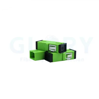
APC (Angled Physical Contact) uses an 8-degree angled end face that bounces back-reflections off into the cladding instead of returning them down the fiber. Return loss exceeds 60 dB. APC is required for any application sensitive to back-reflection - PON systems with video overlay wavelengths, analog video transmission, RF over fiber, and most coherent transmission. APC connector boots are conventionally green.
Why You Cannot Mix UPC and APC
The Four Termination Methods - Which Pairs With Which Connector
The connector tells you what shape goes on the end of the fiber. The termination method tells you how it gets there. Four methods cover essentially all field and factory termination work.
Factory Pre-Terminated Assemblies
Cable is cut to length and terminated with connectors at the factory under controlled conditions, then tested before shipping. Insertion loss is consistently under 0.20 dB, sometimes under 0.15 dB. This is the highest-quality and lowest-effort method, but you must specify lengths in advance and pay a premium. For data center MPO trunks and structured cabling, pre-terminated has become the de facto standard.
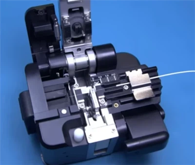
Fusion Splicing to Pigtails
The field cable is cleaved, then fusion-spliced to a factory-terminated pigtail using a fusion splicer that melts the two fibers together with a precise electric arc. This combines field flexibility (any length) with factory-grade connector quality (the pigtail end is pre-terminated). Splice loss typically runs under 0.05 dB, so total insertion loss matches a factory-terminated assembly. This is the gold standard for high-quality field termination.
Mechanical Splicing
Two cleaved fibers are aligned mechanically and held together with index-matching gel and a clamp. Loss is typically 0.10 to 0.30 dB - higher than fusion but acceptable for many applications. Mechanical splicing requires no expensive splicer and no AC power, which makes it useful for emergency repairs and outside plant work where fusion splicing is impractical.
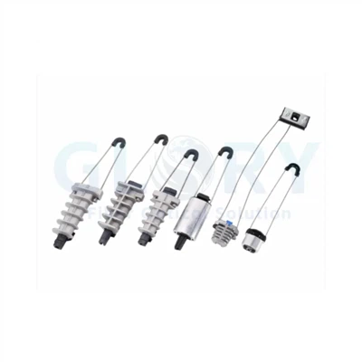
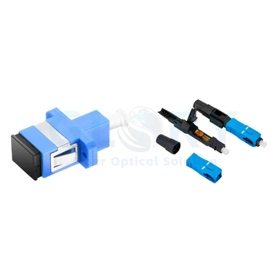
Field-Installable Connectors (No-Epoxy No-Polish)
Also called "fast connectors," these contain a pre-polished fiber stub inside the ferrule and a mechanical splice mechanism inside the connector body. The technician cleaves the field fiber, inserts it, and clamps it - no epoxy, no polishing, no fusion splicer. Insertion loss is typically 0.30 to 0.75 dB depending on cleave quality. They are ideal for FTTH drop terminations, repair work, and any application where speed matters more than absolute lowest loss. See our range of fiber optic tool kits for compatible cleavers and prep accessories.
Cost-Per-Termination Reality Check
Approximate per-termination economics for a typical enterprise build:
| Method | Cost per Termination | Time per Termination | Typical Loss | Best For |
|---|---|---|---|---|
| Factory pre-terminated | $15–$40 | 0 (pull and plug) | ≤ 0.20 dB | Known-length runs, MPO trunks |
| Fusion splice + pigtail | $8–$15 (excl. splicer) | 3–5 min | ≤ 0.20 dB | High-quality field work |
| Mechanical splice | $10–$20 | 2–3 min | 0.10–0.30 dB | Emergency repair, no AC |
| Field-installable connector | $10–$25 | 1–2 min | 0.30–0.75 dB | FTTH drops, fast turnaround |
The fusion splicer itself runs $3,000 to $25,000 depending on grade, which only amortizes over hundreds of terminations. For a one-off job, field-installable connectors usually win on total economics.
Connector Selection by Application
| Application | Recommended Connector | Termination Method | Polish |
|---|---|---|---|
| FTTH drop | SC or LC | Field-installable connector | APC |
| Enterprise LAN backbone | LC duplex | Pre-terminated or fusion + pigtail | UPC |
| Data center 10G/25G | LC duplex | Pre-terminated | UPC |
| Data center 100G/400G | MPO-12 or MPO-16 | Pre-terminated trunk | UPC or APC |
| Hyperscale 800G+ | MPO-16, VSFF | Pre-terminated trunk | APC |
| Industrial / outside plant | Ruggedized LC or ST | Fusion + pigtail | UPC |
| Test & measurement | FC, E2000 | Pre-terminated | UPC or APC |
FTTH and Last-Mile Networks
FTTH deployments overwhelmingly use SC/APC at the customer premises and increasingly LC/APC inside the OLT. The angled APC polish is non-negotiable - PON systems carry video overlay wavelengths extremely sensitive to back-reflections. Field-installable connectors are the dominant termination method for the drop because of speed and labor cost. Our FTTH cable catalog covers compatible connector and cable combinations, including outdoor fiber cables for aerial and underground last-mile runs.
Enterprise LAN
LC duplex with UPC polish is the de facto standard. Pre-terminated MPO trunks feeding LC breakout cassettes have become the dominant structured cabling architecture, and most modern building cabling specs (per TIA-568) assume this topology.
Data Center 10G to 400G
Pre-terminated everything. LC duplex for direct-attach links, MPO trunks for spine-leaf and parallel optics. Match polish to application - most data center fabric is UPC, but APC is increasingly specified for high-bandwidth coherent links and any path that may carry analog or RF traffic.
Hyperscale 800G and Beyond
MPO-16 has won the 800G battle. VSFF connectors are emerging for the highest-density top-of-rack scenarios, especially where transceiver port count constrains the build. APC polish is increasingly the default at this tier because coherent optics require it. 400G and 800G MPO/MTP compatibility charts should always be checked before specifying connector polish.
Industrial and Outside Plant
Ruggedized variants of mainstream connectors dominate - sealed LC with IP67 ratings, ruggedized MPO, and traditional ST in older industrial environments. Fusion splicing to factory pigtails is the preferred termination method because it preserves connector quality despite harsh field conditions.
Single-Mode vs Multimode - How Termination Choice Shifts
The connector form factor is largely fiber-mode-agnostic. You can buy LC, SC, and MPO in single-mode and multimode variants. Polish, color coding, and tolerance specifications differ. Single-mode fiber has a 9-micron core, leaving almost no margin for misalignment - single-mode connectors are held to tighter ferrule tolerances and benefit most from APC polish for any application carrying WDM, analog, or coherent signals. Multimode fiber has a 50-micron core, which forgives small alignment errors. UPC is universal for multimode; APC is essentially never used. Boot color is aqua for OM3/OM4 and lime green for OM5 - be careful with lime green OM5, which is sometimes mistaken for green APC at a glance. Our OS2, OM3, OM4, and OM5 fiber cables - including indoor fiber optic cables - are color-coded per industry convention.
Performance Standards Every Spec Sheet Should Reference
IEC 61753 Grades B, C, D
| Performance Grade | Max Insertion Loss | Min Return Loss | Typical Application |
|---|---|---|---|
| Grade B | ≤ 0.25 dB | ≥ 45 dB | High-performance data center |
| Grade C | ≤ 0.50 dB | ≥ 35 dB | Standard enterprise |
| Grade D | ≤ 1.00 dB | ≥ 26 dB | Legacy / general use |
Always specify a grade. "Low-loss" without an IEC 61754/61753 grade citation is meaningless marketing language. For 400G and above with tight loss budgets, Grade B is essentially mandatory.
TIA-568 Cabling Standards
TIA-568 defines the structured cabling specifications used in commercial buildings across North America. Compliant builds drive the specifications for connector counts, panel layouts, and patch cord lengths, and form the basis for most enterprise procurement.
Real-World Field Data - What Good Looks Like
From our field deployment data across enterprise and data center installations, properly terminated and inspected LC/UPC connectors typically deliver median insertion loss of 0.15 to 0.20 dB, with 95th percentile around 0.35 dB and return loss in the 50 to 55 dB range for UPC and 60 to 65 dB for APC. When field measurements drift above 0.5 dB on an LC connector, the cause is almost never the connector itself - it is contamination on the end face. End-face inspection before every mating should be standard practice.
The Five Most Common Termination Failures
The same five problems account for the overwhelming majority of fiber termination failures we see in the field.
First, contamination - by far the most common cause. A single dust particle on the end face can spike insertion loss above 1 dB. Always inspect with a fiber scope at 200x or 400x magnification before mating, and clean with a one-click cleaner or lint-free wipe with optical-grade solvent. Second, mating UPC to APC - a polish mismatch that physically damages the angled face and produces unrecoverable loss. Third, exceeded mating cycles on patch cables that have been re-plugged hundreds of times in lab and demo environments. Fourth, MPO polarity errors where Type A, Type B, and Type C trunk configurations get mixed across a path. Fifth, bend radius violations near the connector boot that stress the fiber and produce intermittent loss that drives technicians crazy.
How to Choose - A Decision Framework
Start with your transceivers. The optical module dictates the connector - there is no choice on the equipment side. Match what you already have if you are extending an existing network; mixing connector families across a single link path multiplies failure modes. For new builds, default to LC/UPC for enterprise, LC/APC or SC/APC for any PON or RF over fiber application, and MPO-16 for any 400G+ build with a three-year horizon. Specify IEC 61753 Grade B for any performance-critical link. Match polish across an entire link without exception. And for field termination, default to fusion splicing onto factory pigtails when quality matters - field-installable connectors only when speed wins over absolute lowest loss.
Frequently Asked Questions
Q: What is the most common connector used to terminate fiber-optic cabling?
A: The LC connector is the most common type used to terminate fiber-optic cabling in modern networks. Its 1.25 mm ferrule and small push-pull form factor make it the default choice for SFP, SFP+, SFP28, and most QSFP transceivers in data centers and enterprise LANs.
Q: What is the difference between fiber termination and splicing?
A: Termination attaches a removable connector to the end of a fiber, allowing repeated mating and unmating. Splicing permanently joins two fibers end-to-end, either through fusion splicing (which melts the fibers together) or mechanical splicing (which mechanically aligns and clamps the fibers). Most professional installations use both - fusion splicing a fiber pigtail onto the field cable to combine factory-quality termination with field flexibility.
Q: Can you terminate any fiber with any connector?
A: No. The connector must match the fiber type - single-mode versus multimode, and the specific cable jacket diameter. The polish type, UPC or APC, must also match the rest of the link. Mismatched components cause permanent damage or unacceptable insertion loss.
Q: What is the best fiber termination method?
A: Factory pre-terminated assemblies deliver the most consistent low-loss results, typically under 0.20 dB. Fusion splicing to pigtails is the gold standard for field termination, with field-installable connectors offering speed at the cost of slightly higher and more variable insertion loss. The "best" method depends on whether quality, speed, or cost matters most for the specific deployment.
Q: What connector is used for FTTH?
A: FTTH deployments overwhelmingly use SC/APC at the customer premises and increasingly LC/APC inside the OLT. The angled APC polish is essential because PON systems carry video overlay wavelengths extremely sensitive to back-reflections.
Q: How much does fiber termination cost?
A: Per-termination cost in 2026 ranges from roughly $15 to $40 for factory pre-terminated assemblies, $8 to $15 for fusion splicing to pigtails (excluding splicer cost), $10 to $20 for mechanical splicing, and $10 to $25 for field-installable connectors. Total economics depend on volume - a fusion splicer only amortizes across hundreds of terminations.
Q: Why are some connector boots green and others blue?
A: Industry color convention. Blue boots indicate UPC polish for single-mode fiber. Green boots indicate APC polish. The visual distinction prevents the costly mistake of mating UPC to APC, which permanently damages the angled end face.
Authoritative References
- IEC 61754 - Fibre optic interconnecting devices and passive components: IEC International Electrotechnical Commission
- TIA-568 - Commercial Building Telecommunications Cabling Standard: Telecommunications Industry Association
- Fiber Optic Association Termination Reference: The FOA Reference Guide on Termination
- IEEE 802.3 Ethernet Standards: IEEE Standards Association
Related Glory Optics Resources
- LC & SC Fiber Patch Cords
- MPO and MTP Trunk Cables
- Fiber Optic Pigtails
- Fast Connectors (Field-Installable)
- Fiber Optic Adapters
- OS2, OM3, OM4, OM5 Fiber Cables
- FTTH Fiber Cables
- Outdoor Fiber Optic Cables
- Data Center Cabling Solutions
- Fiber Optic Patch Panels
- Fiber Optic Connectors (LC, SC, ST, FC)
- Fiber Optic Tool Kits
- Contact Engineering