If you have ever stood in front of a patch panel holding two cables that look almost identical and wondered why one snaps in and the other does not, you already understand the problem. Fiber optic connectors are the small, often overlooked components that decide whether light travels cleanly from one end of your network to the other - or whether it scatters, reflects, and quietly degrades your signal until something breaks. There are more than a dozen connector types still in active use today, and the right one depends on data rate, environment, density, and what your existing infrastructure already speaks.
This guide walks through every fiber connector type you are likely to encounter in 2026, from the LC connectors filling modern data centers to the legacy biconics still hiding in older telecom closets - with the performance data, application context, and selection logic you need to choose confidently.
Why Fiber Connector Type Matters More Than You Think
A fiber connector does one job: align two glass cores roughly nine micrometers across - about one-tenth the width of a human hair - so that light passes between them with minimal loss. When that alignment is off by even a fraction of a micron, you get insertion loss, return loss, and reflections that can collapse a 100G link into something unusable.
The Real Cost of Choosing the Wrong Connector
Field experience across enterprise and carrier deployments consistently shows that connector-related issues account for a disproportionate share of fiber network problems. According to the Fiber Optic Association's Reference Guide on Connector Identification, contamination and poor termination practice at the connector interface - rather than the cable itself - are the primary causes of optical link failures in the field. The FOA estimates that contamination alone is responsible for the majority of high-loss events on installed fiber plants.
Choosing a connector that is wrong for the environment (for example, a standard LC in a high-vibration industrial setting, or a UPC connector in a PON system that requires APC) compounds this risk significantly. The cost is not just downtime. Replacing a single MPO trunk in a hyperscale data center - factoring in labor, scheduled maintenance windows, and lost capacity - can reach several thousand dollars depending on installation complexity and access constraints. Picking the right connector at the design stage is cheap insurance.
How Connectors Affect Insertion Loss and Network Performance
Every connector mating introduces some optical loss. The IEC 61753 standard defines three performance grades that should appear on any reputable connector datasheet:
| IEC 61753 Grade | Max Insertion Loss | Min Return Loss | Typical Application |
|---|---|---|---|
| Grade B | ≤ 0.25 dB | ≥ 45 dB | High-performance data center |
| Grade C | ≤ 0.50 dB | ≥ 35 dB | Standard enterprise |
| Grade D | ≤ 1.00 dB | ≥ 26 dB | Legacy / general use |
When running a 400G link with a tight loss budget, the difference between a Grade B and a Grade C connector across eight mating points can be the difference between a working link and a flapping interface. Always specify a grade - "low-loss" without a grade citation is meaningless marketing language.
How a Fiber Optic Connector Actually Works
Before comparing types, it helps to understand what every fiber connector - regardless of shape - has in common.
The Five Core Components Every Connector Shares
Every modern fiber connector is built from the same five elements. The ferrule is the precision cylinder (usually ceramic zirconia) that holds the fiber and aligns it. The connector body holds the ferrule and provides the mechanical latching. The boot is the strain relief at the cable entry. The coupling mechanism is what locks two connectors together - push-pull, bayonet, or screw-on. And the alignment sleeve in the mating adapter ensures the two ferrules meet end-to-end.
Ferrule Materials and Why They Matter
Most connectors today use a zirconia ceramic ferrule, prized for its hardness, thermal stability, and ability to be polished to sub-micron precision. Older designs used stainless steel or composite plastic ferrules - these still appear in legacy SMA and some FC connectors but cannot match ceramic for low-loss performance. A small number of specialty connectors use titanium ferrules for harsh-environment deployments where dimensional stability under temperature cycling is critical.
Polish Types Explained - PC, UPC, and APC
Polish type is independent of connector form factor - you can have an LC/UPC, an LC/APC, an SC/UPC, and so on. The polish describes how the end face of the ferrule is shaped and directly determines return loss performance:
- PC (Physical Contact) - slightly domed end face, return loss approximately 35 dB. An older standard rarely specified in new designs.
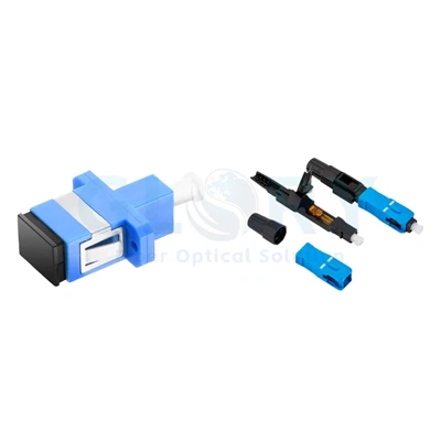
- UPC (Ultra Physical Contact) - more refined dome geometry, return loss ≥ 50 dB per TIA-568. The default for most data and enterprise networks. Connector boots are typically blue.
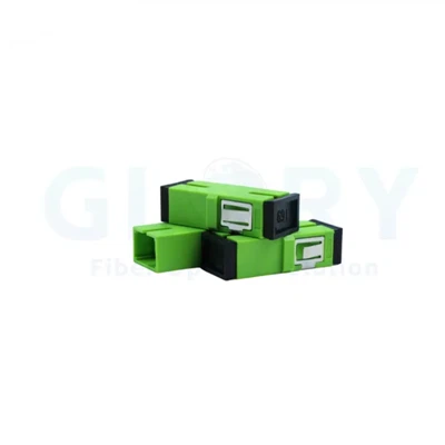
- APC (Angled Physical Contact) - 8-degree angled end face, return loss ≥ 60 dB. Reflections are directed into the cladding rather than back down the fiber. Required for analog video, RF over fiber, and all PON deployments. Connector boots are green.
The 12 Main Types of Fiber Optic Connectors
Dozens of connector designs exist in the historical record, but twelve types account for nearly everything you will deploy or encounter in 2026.
LC Connector (Lucent Connector)
Dominant - New BuildsThe LC connector is the dominant fiber connector in 2026. Developed by Lucent Technologies in the late 1990s, it uses a 1.25 mm ceramic ferrule - half the diameter of an SC - and a small RJ-45-style push-pull latch. Available in simplex and duplex configurations, in both UPC and APC polish, for single-mode and multimode fiber.
Premium-grade LC connectors achieve IEC 61753 Grade B (≤ 0.25 dB insertion loss). Per typical manufacturer specifications, rated mating cycles range from 500 to over 1,000 before measurable performance degradation, depending on ferrule grade and housing quality.
The LC's small footprint allows roughly twice the port density of SC at the same panel size - a decisive advantage when fitting 96 fibers into a single rack unit. Every SFP, SFP+, and SFP28 transceiver uses LC. If you are buying optical modules today, you are buying LC.
SC Connector (Subscriber Connector)
Common - FTTH & Legacy EnterpriseDeveloped by NTT in the 1980s, the SC uses a 2.5 mm ferrule with a square push-pull body. Once the dominant data center connector, it has largely been displaced by LC for high-density applications but remains very common in FTTH - particularly as SC/APC at the customer premises - and in older enterprise installations. Its larger form factor is easier to handle in the field and more resistant to accidental damage, which is why it persists in outdoor and field-terminated deployments.
ST Connector (Straight Tip)
Legacy - Maintenance RotationST connectors use a 2.5 mm ferrule with a bayonet-style twist-lock coupling: push in, twist a quarter turn, locked. Developed by AT&T, they were the workhorse multimode connector of the 1990s and remain in heavy maintenance rotation in legacy enterprise LANs, building risers, and industrial control networks. New installations rarely specify ST, but technicians working on existing infrastructure will encounter them regularly.
FC Connector (Ferrule Connector)
Niche - Test & MeasurementThe FC connector uses a 2.5 mm ferrule with a threaded screw-on coupling. The threading provides superior vibration resistance compared to any push-pull or bayonet design, which is why FC connectors persist in OTDR reference cables, laser sources, spectrum analyzers, and high-precision measurement equipment. They are rarely specified in production networks today but remain a staple in lab environments where accidental disconnection would corrupt a test result.
MTP / MPO Connectors
Dominant - Data Centers 40G+MPO (Multi-fiber Push-On) connectors break the one-connector-one-fiber rule. A single MPO ferrule holds 8, 12, 16, 24, or 32 fibers in a precision-aligned row, enabling the density that modern parallel-optic transceiver standards demand.
MPO-12 remains the workhorse for 40G and 100G parallel optics. MPO-16 has gained rapid adoption for 400G and emerging 800G applications - the 400G-DR4 and 800G-DR8 transceiver standards defined in IEEE 802.3 both align cleanly with MPO-16 lane counts. MPO-24 packs more fiber into the same shell but sees less adoption in new builds because MPO-16 better matches current transceiver architectures.
MTP vs MPO: MTP is a registered trademark of US Conec for an enhanced MPO-compatible connector. MTP connectors mate with standard MPO hardware - they are fully interoperable. The differences are in build quality: MTP uses a removable housing for re-polishing, an improved spring mechanism, and tighter ferrule pin-float tolerances. In practice, MTP-branded connectors typically deliver lower insertion loss and longer service life, but every MTP is also an MPO. If a vendor supplies MTP into an MPO panel, you are fine.
E2000 Connector
Regional - European TelecomThe E2000 is a single-fiber connector with an integrated spring-loaded shutter that automatically protects the ferrule end face when unmated - eliminating contamination risk at the connector interface without requiring a dust cap. Push-pull like LC but using a 2.5 mm ferrule. Common in European telecom networks and high-power laser applications where eye safety and contamination control are regulatory requirements. Rare in North American enterprise deployments.
LX.5 Connector
Niche - Service ProvidersThe LX.5 looks similar to LC but adds a built-in shutter mechanism modeled on the E2000 concept. It uses a 1.25 mm ferrule and is fully push-pull compatible. LX.5 sees use primarily in service provider environments where LC-density and automatic dust protection are both required - a relatively narrow use case that limits its broader adoption.
MT-RJ Connector
Legacy - Early 2000s InfrastructureThe MT-RJ (Mechanical Transfer Registered Jack) was designed as a small-form-factor duplex connector at lower cost than LC. It uses a single rectangular ferrule holding two fibers with an RJ-45-style latch. It enjoyed brief popularity in early-2000s structured cabling before losing the market to LC. You will encounter MT-RJ primarily when retrofitting older installations, not in any new build context.
SMA Connector
Specialty - Industrial & ScientificSMA connectors are screw-on with a threaded metal ferrule, originally adapted from RF coaxial connector geometry. Common in industrial sensing, medical laser delivery systems, and specialized scientific instrumentation where robust mechanical coupling is more important than ultra-low loss. Never specified in mainstream data network infrastructure.
Biconic Connector
Legacy - Pre-1995 Long-HaulThe biconic connector uses a tapered ferrule design and screw-on coupling, and was an early single-mode connector standard in long-haul telecom. Effectively obsoleted by SC and FC by the mid-1990s. If you encounter biconics today, you are working on a network that predates most modern optical standards and should plan for full connector replacement.
VSFF Connectors - SN, MDC, and CS
Emerging - Hyperscale 400G/800GVery Small Form Factor (VSFF) connectors are the next density frontier in hyperscale data centers. The three main competing designs - SN (Senko), MDC (US Conec), and CS (Senko) - all target the same goal: fitting two fiber pairs into the footprint of a single LC duplex connector, enabling true 4-lane breakout from a single QSFP-DD or OSFP port without a breakout fanout.
VSFF adoption is growing in hyperscale facilities running 400G and 800G top-of-rack switching, driven by the density requirements that neither LC nor MPO can address alone. However, VSFF remains rare in enterprise deployments as of 2026, and no single standard has emerged to consolidate the SN / MDC / CS fragmentation. Evaluate carefully before committing to a VSFF infrastructure investment.
Hybrid & Ruggedized Connectors
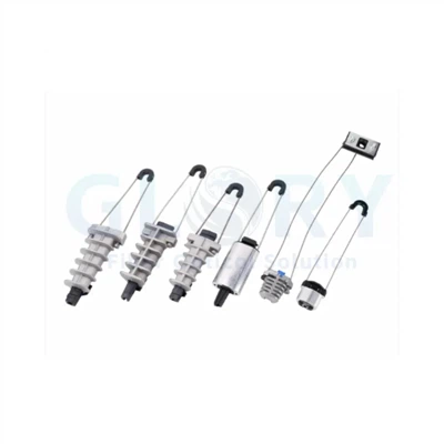
Specialty - Industrial / MilitaryBeyond standardized form factors, hybrid connectors combine fiber with copper or power conductors in a single shell - common in PoE-over-fiber active cabinets and outdoor remote radio head (RRH) deployments in 5G fronthaul. Ruggedized versions of LC, SC, and MPO with sealed shells, positive locking mechanisms, and IP67/IP68 ingress protection ratings serve military, aerospace, and industrial applications where standard commercial connectors fail under vibration, temperature cycling, or moisture exposure.
Single-Mode vs Multimode: How Connector Choice Changes
The connector form factor itself is generally fiber-mode-agnostic - you can get an LC for OS2 single-mode or OM4 multimode. But the polish type, color coding, and ferrule tolerances often differ meaningfully.
OS2 Single-Mode Considerations
Single-mode fiber has a 9 µm core, leaving almost no margin for lateral misalignment. Single-mode connectors are held to tighter ferrule concentricity tolerances and benefit most from APC polish in any application involving wavelength-division multiplexing, analog signals, or PON. Boot color convention: yellow (cable jacket) for single-mode, blue boot for UPC, green boot for APC.
OM3, OM4, OM5 Multimode Considerations
Multimode fiber has a 50 µm core, which is substantially more forgiving of small alignment errors. UPC polish is standard for multimode - APC is essentially never used on multimode fiber. Boot color: aqua for OM3/OM4, lime green for OM5. Note: lime green OM5 is sometimes confused with green APC at a glance; check the jacket color or connector documentation when in doubt.
Application Matrix - Which Connector for Which Job
| Application | Recommended Primary | Acceptable Alternative | Avoid |
|---|---|---|---|
| FTTH / PON | SC/APC | LC/APC | Any UPC |
| Enterprise LAN | LC/UPC duplex | SC/UPC | ST, MT-RJ |
| Data center 10G/25G | LC/UPC duplex | - | SC (density) |
| Data center 100G/400G | MPO-12 / MPO-16 | LC duplex breakout | MPO-24 (new) |
| Data center 800G+ | MPO-16, VSFF | MPO-12 (transitional) | LC duplex |
| Industrial / harsh env. | Ruggedized LC or ST | FC | Standard LC |
| Test & measurement | FC/UPC, FC/APC | E2000 | - |
| Military / aerospace | MIL-spec ruggedized | - | Commercial grade |
FTTH and Last-Mile Networks
FTTH deployments overwhelmingly use SC/APC at the customer premises and increasingly LC/APC inside the OLT. The angled polish is essential because PON systems use video overlay wavelengths that are extremely sensitive to back-reflections - UPC return loss values (≥ 50 dB) are insufficient for RF video overlay, which typically requires ≥ 60 dB (APC territory).
Enterprise LAN and Patch Panels
LC duplex is the de facto standard. Pre-terminated MPO trunks feeding LC breakout cassettes via fiber patch panels have become the dominant structured cabling architecture in modern enterprise builds, replacing individually field-terminated LC runs.
Hyperscale Data Centers (400G/800G)
This is where MPO-16 is winning. The 400G-DR4 and 800G-DR8 transceiver standards defined in IEEE 802.3 both align cleanly with MPO-16 lane counts. VSFF connectors are gaining ground for ultra-high-density top-of-rack scenarios where MPO-16 trunk density is still insufficient.
Industrial, Military, and Harsh Environments
Ruggedized variants of mainstream connectors - sealed LC, MIL-spec MPO - dominate these applications. Waterproof fiber connectors with IP67/IP68 ratings are the right choice for outdoor junction points, antenna site connections, and industrial sensor networks. FC connectors retain a role where threaded vibration resistance is required and density is not a concern.
Insertion Loss, Return Loss & Performance Benchmarks
Field Performance - What "Good" Actually Looks Like
Based on measurement data from enterprise and data center installation work, properly terminated and cleaned LC/UPC connectors typically deliver the following results when tested with a calibrated optical power meter or OTDR per TIA-568 test procedures:
| Metric | LC/UPC (typical) | LC/APC (typical) | MPO-12 (Grade B) |
|---|---|---|---|
| Median insertion loss | 0.15–0.20 dB | 0.15–0.20 dB | ≤ 0.25 dB/connector |
| 95th percentile (field) | 0.35 dB | 0.35 dB | 0.40 dB |
| Return loss | 50–55 dB | 60–65 dB | ≥ 45 dB (Grade B) |
| IEC 61753 Grade | B (≤ 0.25 dB) | B (≤ 0.25 dB) | B |
When field measurements drift above 0.5 dB on an LC connector, the cause is almost never the connector itself - it is contamination. End-face inspection before every mating should be standard practice, not an optional step.
How to Identify a Fiber Connector at a Glance
Color Codes Decoded
| Boot / Jacket Color | Meaning | Fiber Type |
|---|---|---|
| Beige / Off-white | Multimode OM1/OM2 (legacy) | 62.5 µm or 50 µm MM |
| Aqua | OM3 / OM4 multimode | 50 µm MM |
| Lime green | OM5 multimode | 50 µm MM (wideband) |
| Blue (boot) | Single-mode UPC | 9 µm SM |
| Green (boot) | Single-mode APC | 9 µm SM |
| Yellow (jacket) | Single-mode cable (general) | 9 µm SM |
A Visual Decision Flow
If the connector has a tiny push-pull latch and a 1.25 mm ferrule → LC. If it has a square push-pull body and a 2.5 mm ferrule → SC. If it twists to lock → ST. If it screws on with a fine thread → FC, SMA, or biconic. If it has a wide rectangular ferrule with multiple visible fiber tips → MPO or MTP. If it has a small spring-loaded shutter covering the ferrule → E2000 or LX.5.
Common Pitfalls and How to Avoid Them
The Top 5 Connector Failures in the Field
By far the most common cause of high insertion loss - accounting for the majority of measurements above 0.5 dB on installed links. Dust particles as small as 1 µm on a 9 µm single-mode core fully obstruct the optical path. Inspect every connector before every mating with a 200× or 400× fiber inspection scope.
The 8-degree angle mismatch will permanently deform the APC end face on first mating, producing insertion loss values often exceeding 5 dB and rendering the APC connector unusable. Boot color mismatch (blue + green) is the visual warning - stop before mating.
Patch cables that have been re-plugged hundreds of times in active test labs or high-churn environments degrade measurably. Per typical manufacturer specifications, rated mating cycles range from 500 to 1,000+ depending on connector grade. High-cycle connectors should be tracked and retired on schedule.
Type A, Type B, and Type C MPO trunk configurations have different pin arrangements at each end. Mixing polarity types across a link path produces crossed transmit/receive pairs that will never link up - and look identical to a bad connector. Document polarity at installation time.
Routing fiber at sharp angles near the connector boot stresses the fiber inside beyond its minimum bend radius (typically 25–30 mm for standard single-mode). The damage may not show immediately but causes micro-cracks that increase insertion loss over time. Use bend-radius limiters on dense patch panels.
Cleaning and Inspection Best Practices
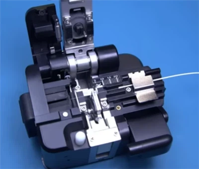
Inspect every connector before every mating - including brand-new factory-terminated connectors, which can have manufacturing residue. Use a fiber inspection scope (200× or 400× magnification) and clean with a one-click cleaner or lint-free wipe with optical-grade IPA solvent. Never blow on a connector end face - moisture and particulates from breath accelerate contamination.
How to Choose the Right Fiber Connector - A Decision Framework
The optical module dictates the connector - you do not get a choice on the equipment side. SFP/SFP+/SFP28 = LC duplex. QSFP breakout = LC duplex. 400G-DR4/800G-DR8 = MPO-16.
Mixing connector families across a single link path multiplies failure modes. Hybrid patch cords and adapters exist, but they add loss and complexity.
PON, RF over fiber, or any analog signal = APC everywhere, including the OLT side. Pure digital data links = UPC is sufficient. Never mix polish types on a link.
Grade C is acceptable for low-traffic or short-reach links. Grade B is required for tight-budget 400G+ links, long-reach single-mode runs, and any link carrying sensitive analog signals.
Outdoor, industrial, or vibration-heavy installations require ruggedized or waterproof connectors. Standard commercial-grade LC and SC are not rated for IP67/68 conditions. See Glory Optics' outdoor connector range for field-ready options.
For complex deployments - multi-vendor environments, high-density data center builds, or mixed single-mode/multimode migrations - the Glory Optics engineering team offers pre-sales consultation on connector selection, loss budgeting, and custom assembly specifications.
Frequently Asked Questions
Q: What are the 4 most common types of fiber optic connectors?
A: LC, SC, ST, and MPO/MTP cover the vast majority of modern installations. LC dominates new builds and transceiver-connected links, SC remains the standard for FTTH and legacy enterprise, ST persists in older LAN infrastructure in maintenance rotation, and MPO/MTP is the standard for all parallel-optic deployments at 40G and above.
Q: Can I mix UPC and APC connectors?
A: No - never. The angled end face of an APC connector will be permanently physically damaged if mated to a flat UPC ferrule, and the resulting insertion loss will make the link unusable. Always match polish type across an entire link. The green vs blue boot color convention exists precisely to prevent this mistake.
Q: Are LC and SC connectors interchangeable?
A: No. They are different mechanical form factors with different ferrule diameters (1.25 mm vs 2.5 mm) and different coupling mechanisms. You can bridge between them using a hybrid LC-to-SC patch cord or an LC/SC hybrid adapter panel, but they do not directly mate.
Q: Which fiber connector has the lowest insertion loss?
A: When properly terminated, cleaned, and inspected, premium-grade LC, SC, and E2000 connectors all reach IEC 61753 Grade B (≤ 0.25 dB). Connector type matters less than termination quality and cleanliness. A contaminated Grade B connector will outperform a clean Grade C connector - but only until it gets dirty.
Q: Why is the APC connector boot green?
A: Industry convention standardized in TIA-568. The angled polish requires unambiguous visual identification to prevent damage from accidental UPC mating. Green is the field warning color that tells technicians this connector requires APC-compatible mating hardware.
Q: How do I know if my connector is single-mode or multimode?
A: Boot color is the fastest indicator: blue or green boot = single-mode; aqua or lime green boot = multimode. The cable jacket color (yellow = single-mode, aqua/lime = multimode) provides a secondary confirmation. When in doubt, read the connector or cable datasheet - boot color conventions are standard but not universally enforced across all manufacturers.
Q: What is the difference between MTP and MPO?
A: MPO is the standard (defined in IEC 61754-7). MTP is a registered trademark of US Conec for a higher-tolerance, field-serviceable MPO connector. MTP and MPO connectors are mechanically interoperable - they mate directly. MTP connectors offer better insertion loss consistency and a removable housing for re-polishing, but both designations refer to multi-fiber push-on technology. In practice, if a vendor quotes you MTP into an MPO panel, it will work.
Authoritative References
- IEC 61754 - Fibre optic interconnecting devices and passive components (International Electrotechnical Commission)
- IEC 61753 - Fibre optic interconnecting devices: Performance standards (Connector performance grades B, C, D)
- TIA-568 - Commercial Building Telecommunications Cabling Standard (Telecommunications Industry Association)
- FOA Reference Guide: Fiber Optic Connector Identification (The Fiber Optic Association)
- IEEE 802.3 Ethernet Standards - 400G-DR4, 800G-DR8 transceiver lane specifications (IEEE Standards Association)