


Why do FTTH connection points matter?
FTTH connection points create the boundaries where fibers are spliced, split, tested, disconnected and replaced. When those points are planned as one system, the ODN is easier to commission and maintain. When they are selected independently, small losses, interface mismatches, contamination and unclear port records can accumulate into subscriber-side failures.
An FTTH optical path is rarely one uninterrupted cable from the OLT to the ONT. It passes through managed connection points in the central office, feeder network, splitting layer, access terminal and subscriber premises.
These points make the network installable and serviceable. They also introduce optical events and physical interfaces that must be included in the project design. Glory Optical's FTTH ODN deployment guide covers the complete passive network; this article focuses specifically on how connection points affect day-to-day deployment quality.
Limitations of Poorly Planned FTTH Connection Points
Cumulative Optical Loss Can Reduce the Usable Margin
A detachable connection works by aligning two polished fiber end faces inside an adapter sleeve. Core offset, angular error, contamination, an end-face gap or damage can increase insertion loss or reflection. One weak connection may appear minor, but several uncontrolled events can consume the margin available to the longest or highest-loss subscriber path.
The project loss budget should therefore include the actual number of splitter stages, mated connector pairs, fusion splices and fiber length. The fiber optic splitter range should be selected together with the surrounding connector and enclosure configuration-not as an isolated component.
Do not approve an FTTH route from average values alone. Review the worst splitter output and the complete worst-case subscriber path, including every accessible connection event.
Inconsistent Termination Creates Field Variability
An FTTH project may legitimately combine fusion-spliced pigtails, factory-terminated drops, hardened outdoor connectors and field-installable connectors. The risk appears when crews choose different methods without a location-based rule.
Permanent cable joints are normally handled inside a protected fiber optic enclosure. Subscriber distribution may use an FTTH termination box, while controlled field termination may use a compatible fast connector. Each location requires its own cable compatibility, sealing, routing and inspection rules.
Poor Documentation Makes Fault Isolation Slower
When an ONT shows low receive power, the fault may be at the splitter output, FDB adapter, outdoor terminal, drop connector, wall outlet or short patch cord. Without continuous labels and baseline measurements, technicians may open several enclosures before identifying the failed segment.
A serviceable connection architecture should let the technician isolate the feeder, splitter, subscriber branch and indoor connection without disturbing unrelated fibers. This is especially important at outdoor access points, where Glory's guide to seven OSP connection-point failure problems explains how sealing, bending, contamination and handling can become long-term loss sources.
Outdoor Interfaces Need Mechanical and Environmental Protection
Outdoor connection points experience more than optical stress. Cable pulling, repeated port access, dust, standing water, UV exposure and poorly secured drop cables can affect the connector or enclosure even when the central optical component is within specification.
The complete interface must be evaluated: housing material, cable entry, port cap, strain relief, connector retention, mounting method and access procedure. A nominally low-loss connector does not compensate for an unsuitable outdoor enclosure or an unsupported cable.
Benefits of Reliable Fiber Connections in FTTH Projects
More Predictable Optical Performance
Reliable connection planning controls where optical loss is introduced and where the network can be opened for service. Protected fusion splices can preserve continuity in permanent feeder routes, while standardized detachable interfaces provide access at distribution and subscriber boundaries.
Connector families and polish types should remain consistent with the operator design. The Glory Optical fiber connector guide explains where SC/APC, SC/UPC and LC interfaces fit; for a PON route, installers must never assume that physically similar APC and UPC interfaces can be mated together.
Faster Subscriber Activation
Pre-connectorized terminals and factory-terminated drop assemblies can move repeatable work away from the field. Fusion-spliced pigtails remain useful inside controlled boxes, while a wall outlet or short ONT patch cord creates a replaceable indoor boundary.
The best architecture is often hybrid rather than fully spliced or fully connectorized. The objective is to minimize skilled field operations at high-volume activation points without adding unnecessary detachable connections elsewhere.
Easier Testing and Maintenance
A well-defined connection map supports staged testing. Technicians can verify the feeder at the ODF, check the splitter input and outputs, isolate an individual access-terminal port, replace a damaged drop and test the final indoor patch without reopening the full route.
Adapters, reference cords and installed connectors should be inspected and cleaned before mating. Unused ports should remain capped, and test records should be tied to the same identifiers used on boxes, splitters, cables and subscriber work orders.
Better Support for Growth and PON Upgrades
FTTH networks are commonly built before every subscriber is activated. Accessible spare ports, organized splitter outputs and documented distribution routes allow homes to be connected in phases without repeatedly disturbing upstream fibers.
The passive ODN may remain in service across multiple generations of active equipment. Stable, clean and serviceable connection points make that reuse more practical by reducing uncertainty during audits and migrations.
Where Fiber Connections Are Used in an FTTH Network
| Network location | Typical connection method | Primary purpose | Main control point |
|---|---|---|---|
| OLT / ODF | Patch cord, adapter and spliced pigtail | Connect active equipment to the passive feeder | Port identification and accessible testing |
| Feeder or distribution closure | Fusion splice | Extend, branch or repair fixed cable routes | Splice protection, routing and enclosure sealing |
| PLC splitting point | Spliced or connectorized splitter | Divide one feeder signal into subscriber paths | Splitter loss, output uniformity and port mapping |
| FDB / NAP | Pigtails, adapters, splices or fast connectors | Organize and distribute subscriber fibers | Entry sealing, bend control and spare-port protection |
| Pre-connectorized terminal | Hardened plug-and-play connector | Speed outdoor drop activation | Connector compatibility, retention and dust caps |
| Drop cable end | Factory connector, fast connector or spliced pigtail | Complete the last subscriber branch | Cable preparation, tensile support and end-face quality |
| Wall outlet / NID | SC/APC adapter and short patch cord | Create a service boundary at the premises | Indoor routing, fiber storage and accessible replacement |
| ONT | Detachable optical connector | Deliver the passive optical signal to active equipment | Correct interface, clean mating and strain-free routing |
These configurations are application examples rather than a universal BOM. Connector type, splitter packaging, enclosure rating and cable structure must follow the operator standard and the actual route design. Browse Glory's complete fiber optic connection components and FTTH cable range when defining the interface between each segment.
FTTH Connection-Point Planning Checklist
Before finalizing the BOM, define the connection architecture across the full OLT-to-ONT route:
- Mark every permanent splice, detachable connector and splitter stage on the route drawing.
- Define one approved connector and polish type for each network segment.
- Confirm cable compatibility for fast, hardened and factory-installed connectors.
- Separate permanent infrastructure from components expected to be replaced later.
- Specify ingress protection, cable sealing and strain relief for every outdoor point.
- Reserve practical access for connector inspection, cleaning and optical testing.
- Create continuous labels from splitter output to access port and subscriber address.
- Require per-port or per-route acceptance records instead of only batch-level values.
For configured boxes, list the enclosure, splitter, adapters, pigtails, connector polish, cable-entry range, port caps, labels and test evidence in one BOM. Purchasing these as unrelated line items increases the chance of mechanical or interface mismatch.
Recommended Glory Optical Products for FTTH Connection Points
The following products represent four different connection boundaries in an FTTH route. Final models, port counts and interfaces should be matched to the actual ODN drawing.

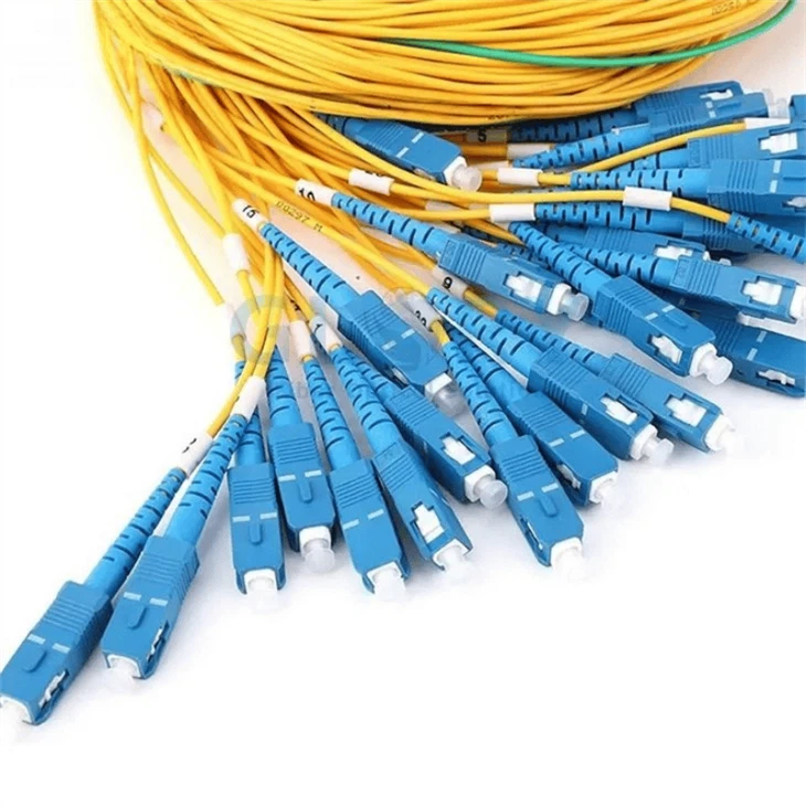


Configured FTTH boxes may also require matching fiber optic pigtails, fiber adapters and patch cords. Confirm connector polish, fiber grade, length and port numbering across the assembled system.
FTTH Fiber Connection FAQs
Q: Why are connection points important in an FTTH network?
A: Connection points create the practical boundaries where fibers are divided, terminated, tested, disconnected or replaced. Their design affects optical loss, reflection, installation speed, environmental protection and future maintenance.
Q: Should every FTTH connection use a detachable connector?
A: No. Protected fusion splices are often preferred for permanent feeder and distribution joints, while detachable connectors are useful where testing, subscriber activation, replacement or reconfiguration is expected.
Q: Where is SC/APC commonly used in FTTH?
A: SC/APC is commonly used at PON-facing adapters, splitter outputs, distribution terminals, wall outlets and ONT interfaces when required by the operator specification. The same optical path should not mix APC and UPC interfaces.
Q: How can FTTH projects reduce connector-related loss?
A: Define approved interfaces, control the number of mated pairs, inspect and clean end faces before mating, protect unused ports, record acceptance results and investigate the worst subscriber path rather than relying only on average measurements.
Q: What information should be included in an FTTH connection-point RFQ?
A: Specify the network location, port count, connector and polish type, splitter configuration, cable type, ingress protection, mounting method, labeling, pigtail length, test-report requirements and whether components must be factory pre-installed.
Conclusion
FTTH reliability is shaped at every place where fiber is spliced, divided, terminated or reconnected. A good architecture uses permanent splices where continuity is required, detachable interfaces where testing or replacement is expected, and protected connector systems where the network is exposed outdoors.
Planning these points as one system helps preserve optical margin, standardize field work, accelerate subscriber activation and create clear maintenance boundaries from the ODF to the ONT.





