Sticklok Connector – The "20 vs. 90 minutes" Difference in Field Work
"One installer described it as the difference between a 20‑minute job and a 90‑minute job."
The Traditional Field Termination Workflow

A routine outdoor fiber termination using a fusion splicer typically involves:
1.Setup – Unpack and warm up the splicer, clean electrodes (5 min).
2.Cable preparation – Strip outer sheath, remove strength members, clean bare fiber (5‑8 min).
3.Cleaving – Cleave the fiber with a precision cleaver (1‑2 min).
4.Splicing – Align and fuse the fiber to a pigtail or another fiber (2‑3 min).
5.Protection – Slide a heat‑shrink sleeve over the splice, place in oven, wait for cooling (4‑5 min).
6.Testing – Verify with an OTDR or power meter (3‑5 min).
7.Enclosure sealing – Store the splice, close and seal the box (5‑10 min).
Total elapsed time easily reaches 60–90 minutes per termination, not including travel, ladder setup, or weather delays. Add a second attempt if the first splice fails.
The Sticklok Workflow
The Sticklok connector changes that workflow:
1.Cable preparation – Strip the cable (same as above, ~3 min).
2.Insert fiber – Insert the bare fiber into the pre‑loaded connector until it contacts the factory‑polished stub.
3.Lock – Push the connector body; an internal mechanical splice locks automatically (no tools).
4.Test (optional) – Quick visual or power meter check (<1 min).
Total time: 15–20 minutes, including cable prep. No splicer, no oven, no glue, no waiting for weather.

Real‑World Impact
For a project with 500 outdoor termination points:
1.Traditional method: 500 × 75 min = 37,500 minutes = 625 hours of field labour.
2.Sticklok method: 500 × 18 min = 9,000 minutes = 150 hours of field labour.
3.Labour saving: 475 hours (equivalent to 12 weeks of a full‑time technician).
Moreover, because Sticklok is tool‑less and immune to dust/wind, you can work through light rain and breezes that would force a splicer operator to stop. This reduces project overruns due to weather.
2. Small Footprint – One Size Smaller Handhole = Real Civil Savings
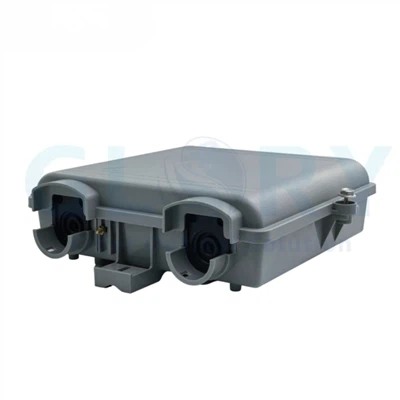
Marvel terminals are surprisingly compact. For example, the 1:8 two‑layer MTS version measures only 154 × 82 × 47.5 mm – roughly the size of a paperback book. Even the largest configuration (24F MTC) is still far smaller than traditional metal splice closures.
How Handhole Size Affects Budget
Typical handhole categories:
|
Type |
Inner Size (approx) |
Typical Cost (material + excavation) |
Suitable for Marvel? |
|
Small handhole |
400×400 mm |
80–120 |
Yes (fits 3 4 terminals) |
|
Medium handhole |
600×600 mm |
150–220 |
Yes (fits 8 10) |
|
Large vault |
800×800 mm |
300–450 |
Overkill for Marvel |
Excavation cost often scales non‑linearly. A medium handhole may require 50% more digging and twice the concrete compared to a small one.
3. MTT Series – Cascading with Stable Insertion Loss
In MDUs, hotels, or ring topologies, you need to tap off a portion of the optical power for local users while passing the remaining signal upstream. Traditional solutions use two‑stage splitters (e.g., 1:4 at each floor) or passive couplers, but they introduce cumulative loss that grows with every floor.
The MTT series (TAP versions) solves this with:
• Uniformity options: 70:30 and 50:50
• Tap ratios: 1:3 up to 1:17 (70:30); 1:3 up to 1:17 (50:50)
• Key parameter: Cascade insertion loss ≤2.6 dB (constant across all tap ratios)
Why Constant Cascade Loss Matters
Consider a 10‑floor MDU, each floor with a 70:30 MTT tap (1:9 configuration). The 30% tap goes to the floor's ONT; the 70% continues upward.
• Traditional mismatched coupler: Loss per floor might be 3.5 dB on the through path, leading to 35 dB loss at the 10th floor – impossible for any receiver.
• MTT approach: Each floor adds ≤2.6 dB cascade loss. Total at 10th floor ≈ 26 dB – still within the power budget of a typical GPON system (28–30 dB margin from OLT).
Moreover, because the cascade loss is identical for every floor, link budget calculations become trivial: multiply the per‑floor loss by the number of floors. No need to re‑engineer for different tap ratios per level.
Link Budget Example
Assume:
• OLT output: +5 dBm
• Splitter loss (1:32): 17 dB
• Fiber attenuation: 0.35 dB/km × 2 km = 0.7 dB
• MTT per floor cascade loss: 2.6 dB
• 10 floors total cascade loss: 26 dB
• Drop port loss at each floor: ≤19.7 dB (1:17 configuration)
Worst‑case floor (10th):
Received power at ONT = 5 − 17 − 0.7 − 26 − 19.7 ≈ –58.4 dBm – well above the typical ONT sensitivity of –27 dBm. In fact, the margin is so high that you could use a 1:32 splitter before the cascade, or increase the number of floors to 15–20 without touching the power budget.
This predictability allows network designers to standardise on one MTT model across an entire MDU, simplifying ordering and spares.
4. Total Cost of Ownership – Beyond the Purchase Price

TCO for outdoor terminals has three main components: acquisition, installation, and maintenance (plus civil works covered above).
Acquisition
Marvel terminals are priced competitively with mid‑range pre‑connectorized products. Low‑cost alternatives exist, but they typically lack IP68 sealing, UV resistance, or the cascade performance of MTT.
Installation – Hidden Labour Savings
Let's compare a 500‑node FTTH project using two methods:
|
Cost Element |
Traditional (Field Splice) |
Marvel (Sticklok) |
|
Time per node (labour) |
75 min |
18 min |
|
Total labour hours |
625 hrs |
150 hrs |
|
Labour cost @ $40/hr |
$25,000 |
$6,000 |
|
Fusion splicer rental/depreciation |
$3,000 |
$0 |
|
Splicer consumables (cleaver blade, electrodes) |
$1,500 |
$0 |
|
Weather related delays (estimated) |
15% extra labour |
0% |
|
Total field cost |
~$34,000 |
~$6,000 |
Savings: $28,000 (82% reduction)
5. Selection Guide – MTC, MTS, or MTT? Which Node Uses Which?
Choosing the correct series avoids over‑engineering (paying for features you don't need) or under‑engineering (causing field failures).
|
Core Function |
Typical Use Case |
Key Parameters |
Example Deployment |
|
|
MTC |
Cable termination (branch or splitter) |
Simple tap points, multi drop, feeder to distribution |
4F to 24F, single/two layer, loss ≤0.45 dB |
Rural roadside cabinet, 12 home cluster |
|
|
MTS |
Standalone splitter for PON |
GPON/XGS PON distribution points |
Split ratios 1:2 to 1:16, compact housing |
Street cabinet serving 32 64 homes, 1:8 or 1:16 split |
|
|
MTT |
TAP for cascade architectures |
MDU, ring topologies, inline monitoring |
70:30 / 50:50, cascade loss ≤2.6 dB |
10 storey apartment, one per floor |
Quick Decision Flowchart
1.Do you need to split the signal for multiple users in ONE location? → Yes → Use MTS (standalone splitter).
2.Do you need to cascade through several floors/towers, tapping off a small portion at each? → Yes → Use MTT (TAP).
3.Otherwise (just a simple break‑out from a feeder cable, no splitting or minimal splitting) → Use MTC branch version.
Conclusion: One Family, Five Advantages
The Marvel pre‑connectorized terminal family is not just a collection of boxes. It is a coherent system that addresses the five most pressing concerns in ODN deployment:
1.Speed – Sticklok turns 90 minutes into 20, slashing field labour by 80%.
2.Space – Small footprint allows one‑size‑smaller handholes, saving thousands in civil works.
3.Cascade predictability – MTT keeps cascade loss constant (≤2.6 dB), no matter how many nodes.
4.TCO – Lower installation, maintenance, and civil costs justify a premium – often delivering 6‑figure savings over a few hundred nodes.
5.Clarity – MTC, MTS, MTT give you a clear selection matrix for every node type (branch, split, cascade).
If you are tired of field splicing delays, oversized vaults, unpredictable cascade losses, and hidden maintenance costs, it is time to take a fresh look at what a modern pre‑connectorized terminal can do.