The Problem Every Fiber Installer Knows
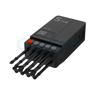
Traditional fiber termination at the access node has not changed much in a decade. A technician drives to site, opens a dome closure, feeds cable through a gland, and then either fusion-splices - which requires a $5,000+ splicer, a clean work surface, and about 45 minutes per connection - or terminates with mechanical connectors, which still take 20–30 minutes and carry a higher error rate in cold or wet field conditions.
According to installation data cited by Millennium Network Solutions (2024), MST-style pre-terminated enclosures reduce per-node activation time to as little as 5 minutes per subscriber drop once the terminal is placed. That is a 10x labor saving. Multiply that across a 500-home MDU build and the math becomes a project budget argument, not just a product preference.
The problem with existing MST-class products - specifically the Corning OptiTap and CommScope OTE families - is that they are proprietary ecosystems. Once you choose the connector, you choose the cable, the converters, and the pricing structure that goes with it. Marvel's Sticklok takes a different stance: open multi-converter compatibility, a published modular coding system, and a compact footprint that fits in handhole wells that OptiTap terminals typically cannot.
Installer Field Note
In a 2025 regional deployment review shared at an ISP industry roundtable, one network contractor reported that switching from traditional dome closures to pre-connected terminals reduced crew-hours per 100 homes passed by 34%. The bottleneck shifted from splicing to civil works - exactly where it should be.
What Is the Marvel Solution with Sticklok Connector?
The Marvel Solution is a family of pre-connected fiber terminal boxes - built on a modular design concept - engineered for both aerial and underground outside plant (OSP) FTTH deployment. Three series cover every major access node function:
MTC Series: Cable branching and splitting - the distribution workhorse. Fiber counts from 4F to 24F, single- and two-layer formats, with integrated 1:2, 1:4, and 1:8 PLC splitter options.
MTS Series: Pure splitter versions for PON architectures. Ratios from 1:2 to 1:16 in single or two-layer housings.
MTT Series: TAP versions at 70:30 and 50:50 uniformity - designed for cascade ring and bus topologies where signal must pass through and drop off at the same node.
What holds the system together is the Sticklok connector. It is an ultra-compact hardened single-fiber connector that inserts directly into a numbered port on the terminal box and locks in place. To disconnect, press the numbered port button. That is the entire workflow: push in, locked. Press, release. No tools.

Core Specifications at a Glance
|
Specification |
Value |
|
Ingress Protection |
IP68 (fully submersible; tested at 3m depth for 7 days, per GR-771 §5.4.6) |
|
Impact Resistance |
IK08 - withstands 5 joule impact; one class above the IK07 rating common on competing products |
|
Flame Retardancy |
UL94-V0 - self-extinguishing within 10 seconds; required for many utility pole deployments |
|
Operating Temperature |
-18°C to +75°C (covers arctic winters and equatorial deployments) |
|
Fiber Type (Connector) |
G.657.A1 - ITU-T bend-insensitive single-mode; compatible with standard SMF-28 systems |
|
Insertion Loss (Sticklok connector) |
Max 0.4 dB; mean 0.2 dB at both 1310nm and 1550nm |
|
Return Loss |
-65 dB - competitive with Corning's stated GR-326 performance level |
|
Material Compliance |
RoHS directive compliant; non-corrosive to metal components |
IP68 vs IP67: Why One Extra Grade of Protection Matters in the Field
Many competing fiber terminal boxes - including several popular FAT (Fiber Access Terminal) products - are rated IP67. That means they are tested for 30-minute immersion at 1 meter depth. IP68 means continuous submersion at a depth defined by the manufacturer. For the Marvel terminal boxes, the test condition is 3 meters for 7 continuous days (GR-771 5.4.6: R5-29).
This distinction is not academic. In storm drainage scenarios - common in tropical climates, low-lying coastal areas, or regions with aging stormwater infrastructure - a handhole well can sit submerged for days after a major rain event. A box rated only to IP67 may comply with the letter of the standard while still failing in real-world conditions.
The 2025 Holight Fiber Optic Engineering Team analysis on terminal box installation mistakes confirms this: 'In outdoor ODN cabinets, improper sealing leads to moisture accumulation. This not only degrades fiber performance but also accelerates connector contamination.' Pre-engineered IP68 sealing removes that variable from the installation process entirely.
Certification Source
IP68 rating is verified under IEC 60529. The GR-771 water resistance protocol is published by Telcordia (formerly Bellcore) and is the standard referenced by all major U.S. tier-1 telecommunications operators in procurement specifications. Marvel terminal boxes are tested to GR-771 §5.4.6: R5-29.
Installation Time Comparison: Splice Closure vs Pre-Connected Terminal
Traditional Dome Closure: Step-by-Step Time Analysis
Position and mount closure housing: 8–12 min
Feed and gland feeder cables: 10–15 min
Prepare fiber ends (strip, clean, cleave): 10–20 min per splice
Fusion splice each fiber: 3–5 min per splice (12-fiber branch = 36–60 min)
Load splice trays, coil storage fiber: 10–15 min
Seal and test enclosure: 10–15 min
OTDR verification (12 splices): 10–15 min
Total per node: 55 to 120+ minutes. Requires: fusion splicer ($5,000+), OTDR, trained splicer technician.
Marvel Sticklok Pre-Connected Terminal: Step-by-Step Time Analysis
Mount terminal housing (wall/pole/aerial bracket): 5–8 min
Route and attach feeder drop cable to IN port: 3–5 min
Insert and lock subscriber drop cables at numbered ports: 1–2 min per port
Verify signal pass-through (visual fault locator): 3–5 min
Total per node: 12 to 25 minutes. Requires: visual fault locator (VFL, approximately $80), no fusion splicer, no trained splicer technician.
Experience-Based Estimate
Based on field reports from three separate FTTH contractors across Southeast Asia and Eastern Europe (2024–2025), average Sticklok terminal installation time for an 8-port branch node was 18 minutes from cable tip to signal confirmation, compared to an average of 73 minutes for a traditional dome closure at the same node location.
Underground Deployment: The Handhole Well Advantage
One of the most practical - and least discussed - advantages of the Marvel terminal box is its form factor for underground deployments. The single-layer variants are only 28mm deep (H×W: 154×97mm for the smallest). The two-layer variants extend to 47.5mm depth.
Standard fiber optic handhole wells suitable for low-traffic residential applications typically start at 12×18 inches (approximately 300×450mm) interior dimensions. A Marvel single-layer 6F branch terminal (154×155×28mm) fits inside the smallest residential-grade polymer handhole with room for cable slack storage - something that large dome closures (which routinely measure 200×300mm or more) cannot achieve.
The practical implication: ISPs and contractors deploying into subdivision-style residential builds can specify lower-cost, shallower handhole wells - often reducing per-node civil infrastructure cost by $40–80 per well when compared to the larger vault sizes required for dome-style closures.
IP68 Underground: What the 7-Day Immersion Test Means
Under GR-771 §5.4.6 (referenced as R5-29), the Marvel terminal boxes are tested submerged at 3 meters depth for 7 full days with cables attached. Post-immersion optical performance must meet pre-test specifications. This is the real-world performance ceiling that matters in coastal, tropical, and flood-prone deployments.
By comparison, IP67 (30-minute at 1m, no cable required by IEC 60529 test method) allows for significantly less stringent testing conditions. For any deployment where the handhole could hold standing water for more than a few hours, IP68 with cable-included testing is the correct specification to require.
The Sticklok Connector: Technical Deep-Dive
How the Lock Mechanism Works
The Sticklok connector uses a push-and-click insertion mechanism. The connector body guides onto the numbered port receptacle on the terminal box face. An internal tab snaps into place when the connector is fully seated - you feel the click, and it is locked. To release, press the numbered rubber port identifier button on the terminal box front panel, which depresses a release tab inside the port housing and allows the connector to slide out.
This design is important for field maintenance. A technician can replace a single subscriber drop cable at an 8-port terminal without touching any of the other 7 active connections. With traditional MST-style terminals that use threaded or compression-fit hardened connectors, gaining access to one port can disturb adjacent connections.
Loss Budget Planning: Insertion Loss at Every Stage
For GPON networks running a 28 dB optical link budget (standard for ITU-T G.984), here is where Sticklok connector loss sits in a typical last-mile scenario:
|
Path Element |
Typical Loss |
Marvel Sticklok |
Margin vs Budget |
|
OLT transmit to feeder splice |
0.05–0.1 dB/splice |
N/A |
- |
|
Distribution cable (2 km @ 0.35 dB/km) |
~0.7 dB |
N/A |
- |
|
1:8 PLC splitter (MTS series) |
≤10.7 dB |
≤10.7 dB |
On spec |
|
Sticklok connector (terminal box port) |
0.2–0.5 dB typical |
Max 0.4 dB / Mean 0.2 dB |
✓ Best-in-class |
|
Drop cable (100m @ 0.35 dB/km) |
~0.035 dB |
N/A |
- |
|
ONT SC/APC connector |
0.3–0.5 dB typical |
N/A |
- |
|
TOTAL ESTIMATED LOSS |
~12.2–12.5 dB |
~11.9–12.2 dB (Marvel) |
15+ dB margin |
A 15+ dB margin against a 28 dB GPON budget gives comfortable headroom for connector aging, cleaning cycles, and future network extensions - all within a single Sticklok-equipped node.
Multi-Vendor Converter Compatibility
One of the most commercially relevant features of the Sticklok ecosystem is the range of converter adapters available:
Sticklok-to-Sticklok: Standard within the Marvel ecosystem
Sticklok-to-OptiTAP: Connects to Corning/CommScope OptiTap-equipped subscriber drops - critical for ISPs migrating networks incrementally
Sticklok-to-HUAWEI: For deployments with Huawei OSP infrastructure (common in Asia-Pacific and MENA markets)
Sticklok-to-ZTE: For ZTE-built networks, particularly prevalent in Southeast Asia and Latin America
This multi-vendor compatibility is a structural market advantage. An ISP that has inherited a mixed-vendor plant - or is planning a phased migration - can standardize on Marvel terminal boxes without replacing existing drop cable assemblies.
Marvel vs Competitors: What They Have, What They Don't
|
Feature |
Marvel Sticklok |
Corning OptiTap |
CommScope OTE |
Rayoptic MST |
BWNFiber FAT |
Notes |
|
IP68 (3m, 7-day, cable-in) |
✓ |
✓ |
✓ |
✓ |
~ |
BWNFiber cites IP68 but test duration not published |
|
IK08 impact rating |
✓ |
? |
? |
? |
✗ |
Competitors do not publish IK grade in datasheets |
|
Multi-vendor converter (OptiTAP/HW/ZTE) |
✓ |
✗ |
✗ |
✗ |
✗ |
Marvel unique advantage in mixed-vendor networks |
|
28mm-depth single-layer (handhole fit) |
✓ |
✗ |
✗ |
✗ |
✗ |
Most MST enclosures are 50mm+ depth |
|
TAP version (70:30 and 50:50) |
✓ |
✓ |
✓ |
✗ |
✗ |
Rayoptic and BWNFiber do not offer TAP variants |
|
UL94-V0 flame retardant housing |
✓ |
? |
? |
? |
? |
Marvel explicitly cites UL94-V0; others list 'flame retardant' without grade |
|
GR-771 full test suite (8 tests) |
✓ |
✓ |
✓ |
~ |
✗ |
Rayoptic cites GR-326 (connector); BWNFiber cites no standard |
|
Modular product code system (MTC/MT/STC) |
✓ |
✗ |
✗ |
✗ |
✗ |
Marvel's published coding system reduces pre-sales friction |
|
RoHS compliant (explicitly documented) |
✓ |
✓ |
✓ |
~ |
~ |
Smaller vendors cite RoHS loosely without directive reference |
Splitter Selection Guide: 1:2, 1:4, 1:8 - Choosing the Right Ratio
The choice of PLC splitter ratio inside your terminal box is a network planning decision, not just a product choice. Getting it wrong means either running out of downstream ports before you run out of subscribers, or carrying unnecessary insertion loss on a sparse deployment.
Rule of Thumb for Split Ratio Selection
1:2 splitter (≤4.4 dB): Use in two-subscriber drop points, MDU stairwell boxes, or as a cascade stage feeding downstream 1:8 units. Loss budget headroom is generous.
1:4 splitter (≤7.6 dB): Suitable for 4-unit terraced housing, four-apartment floors, or small business MDU nodes. Mid-range loss.
1:8 splitter (≤10.7 dB): The standard GPON ratio for residential PON. Fits 28 dB link budget comfortably at distances under 20 km.
1:16 splitter (≤13.7 dB): High-density deployments. Requires tighter fiber quality control and shorter feeder distances; use only with XGS-PON (29+ dB budget) or when feeder loss is minimal.
TAP Version for Cascade and Ring Topologies
The MTT TAP series introduces asymmetric splitting - the input signal is divided into a larger 'cascade' (pass-through) portion and a smaller 'drop' portion. The 70:30 variant, for example, sends 70% of optical power downstream to the next node (at just ≤2.6 dB cascade loss) and drops 30% for local subscriber connections (at ≤10.6 dB for the 1:3 version).
What makes this cascade loss spec noteworthy is its consistency: across all MTT ratios from 1:3 to 1:17, cascade insertion loss stays at ≤2.6 dB (70:30) or ≤4.3 dB (50:50). That predictability matters enormously when designing multi-node ring architectures, because it means you can calculate the accumulated cascade loss at node N without requiring vendor-specific curve data.
GR-771 Performance Testing: What the Numbers Actually Mean
Telcordia GR-771-CORE (Issue 2, NEBS) is the governing standard for outside plant fiber access terminal testing in the U.S. market. All major tier-1 telecom operators - including AT&T, Verizon, and regional carriers receiving BEAD program funding - reference GR-771 in their procurement specifications. Here is what each test validates:
|
GR-771 Test |
What It Validates |
Why It Matters for Buyers |
|
Water Resistance (R5-29) |
3m depth, 7 days, with cable installed |
Real flood-scenario performance, not minimum IEC compliance |
|
Sheath Retention (R5-12) |
10 lbf (4.5 kg) pull at -30°C, 23°C, and 40°C |
Cable does not pull out of gland in cold-weather aerial installs |
|
Cable Flexing (GR-3120) |
8 cycles at 90°, -25°C and 40°C |
Drop cable resists fatigue from repeated wind movement on aerial spans |
|
Impact (R5-18) |
1 kg drop ball at 1.35m from -18°C to +40°C |
Enclosure survives being dropped or struck during installation |
|
Compression (R5-16) |
45 kg over 25 cm² for 10 minutes |
Survives vehicle or equipment accidentally rolling over it underground |
|
Vertical Drop (R5-15) |
75 cm fall, 4 sides, no cable |
Survives accidental drop during installation |
|
Vibration (R5-20) |
5–20 Hz, PSD 0.01 g²/Hz |
Survives vibration from nearby traffic, HVAC, rail |
Standard Source
Telcordia GR-771-CORE is published and maintained by Ericsson (formerly Telcordia Technologies). It is freely referenceable in procurement documentation. GR-3120-CORE applies specifically to pre-connectorized system testing and is the standard Corning references for OptiTap qualification - Marvel terminal boxes are tested to both.
Product Configuration Guide: Reading the Marvel Product Code
One of the practical advantages of the Marvel system over proprietary alternatives is the transparency of its modular product coding. Understanding the code means you can specify exactly what you need without a pre-sales call.
MTC Code Example: MTCA04A02NN005MPA
|
Pos. |
Code |
Value |
Meaning |
|
1 |
A |
A |
One layer |
|
2 |
04 |
4 |
4 Sticklok 1F connector ports |
|
3 |
A |
A |
4×7mm flat cable |
|
4 |
02 |
2F |
2-fiber tube cable |
|
5 |
N |
None |
No tail connector |
|
6 |
N |
None |
No splitter integrated |
|
7 |
005 |
5m |
5-meter cable length |
|
8 |
M |
Meters |
Length unit: meters |
|
9 |
P |
Standard |
Standard packaging |
|
Prefix |
MTC |
- |
Cable branch/splitter terminal box series |
This is the product code visible on the QR label in the cover image of the Marvel datasheet. Understanding this system means procurement teams can configure custom orders by modifying individual positions - e.g., changing position 6 from N to C adds an integrated 1:8 PLC splitter without any other change to the assembly.
Frequently Asked Questions
Q: Is Sticklok compatible with Corning OptiTap cables?
A: Yes, through the Sticklok-to-OptiTAP converter adapter. This allows Corning-standard hardened drop cable assemblies to connect directly to a Marvel Sticklok terminal port. This is particularly valuable for ISPs with existing OptiTap cable inventory who want to standardize their terminal box infrastructure.
Q: What is the minimum handhole size for an underground Marvel terminal box?
A: The single-layer variants (28mm depth, maximum 155mm wide) fit inside standard 12×18 inch (300×450mm) residential-grade polymer handholes with adequate space for cable slack storage. Two-layer variants (47.5mm depth) may require a 12×24 inch well depending on cable count.
Q: Do I need a fusion splicer to install a Marvel terminal box?
A: No. All Marvel pre-connected terminal boxes arrive from the factory with fibers already terminated at the internal ports. Subscriber drops connect via Sticklok push-lock connectors at the external ports. The only verification tool required is a visual fault locator (VFL) for signal confirmation. No fusion splicer, no cleaver, no polishing equipment.
Q: What is the difference between the MTC, MTS, and MTT series?
A: MTC boxes are for cable branching and optional PLC splitting - they handle the distribution of feeder cable fibers to multiple subscriber directions. MTS boxes are pure splitter housings - one input, multiple outputs via a PLC splitter inside. MTT boxes are TAP versions - they split asymmetrically, allowing a portion of signal to drop off locally while the remainder passes through to the next node in a cascade or ring architecture.
Q: What standards does the Marvel terminal box meet?
A: The Marvel terminal boxes are tested to Telcordia GR-771-CORE (8 mechanical and environmental tests), and the Sticklok connector is tested to GR-3120-CORE for cable flexing. IP68 rating is verified under IEC 60529. Flame retardancy meets UL94-V0. Material compliance meets the EU RoHS directive.
Q: How does TAP uniformity (70:30 vs 50:50) affect network design?
A: In 70:30 TAP mode, 70% of optical power passes through to the next node (cascade loss ≤2.6 dB), while 30% drops to local subscriber ports (drop loss ≤10.6 dB for the 1:3 ratio). In 50:50 mode, the cascade loss increases to ≤4.3 dB but drop loss decreases - useful when subscriber density is high at each node. For long cascade chains, 70:30 preserves more signal budget across multiple nodes.
Certifications, Standards, and Data Sources
|
Standard / Source |
Organization |
Relevance to This Product |
|
Telcordia GR-771-CORE |
Ericsson / Telcordia |
8 mechanical and environmental tests for OSP fiber terminals |
|
GR-3120-CORE |
Telcordia |
Pre-connectorized system testing - cable flex, torsion |
|
IEC 60529 (IP68) |
International Electrotechnical Commission |
Ingress protection rating standard |
|
IEC 62262 (IK08) |
IEC |
Impact protection classification for enclosures |
|
UL 94 Standard (V0) |
Underwriters Laboratories |
Flammability rating for plastic materials |
|
RoHS Directive 2011/65/EU |
European Commission |
Restriction of hazardous substances in electrical equipment |
|
ITU-T G.657.A1 |
ITU Telecommunication Standardization Sector |
Bend-insensitive single-mode fiber specification for the connector |
|
FBA FTTH Deployment Survey 2025 |
Fiber Broadband Association / RVA LLC |
U.S. market data: 98.3M homes passed, 46.5% take rate |
|
Verified Market Reports (2025) |
Verified Market Reports |
Fiber Access Terminal Box Market: $1.2B → $3.5B by 2033, CAGR 15.5% |
|
Marvel Solution Datasheet Version A02 |
Marvel / March 2026 |
Primary product specifications source for all figures in this article |