|
What is FTTH? (Quick Definition) FTTH (Fiber to the Home) is a broadband network architecture that delivers a dedicated optical fiber connection directly to a residential or commercial premises, enabling gigabit-class internet speeds with minimal signal loss over distances up to 20 km. |
If you are planning an FTTH deployment - whether a single dwelling or a multi-home rollout - the quality of your installation determines network performance for the next 25+ years. This guide gives you the exact steps, measurements, and standards used by certified FTTH installers, so you can get it right the first time.
Table of Contents
Step 1: Choose the Right Deployment Method for Your Environment
Step 2: Plan the Route - Survey, Permits & Utility Marking
Step 3: Select and Handle FTTH Cable Correctly
Step 4: Pull the Cable (Conduit, Aerial & Direct-Buried)
Step 5: Splice the Fiber - Fusion or Mechanical
Step 6: Terminate and Connect to Distribution Equipment
Step 7: Test Everything - OLTS, OTDR & VFL
Tools & Equipment Reference Table
Step 1: Choose the Right Deployment Method for Your Environment
Selecting the wrong installation method is the single most common cause of premature cable failure. Match the method to the terrain:
Aerial (overhead, pole-mounted): Use for suburban deployments where poles already exist. Critical spec: tension control to prevent sag - calculate wind and ice loading per ANSI/TIA-590. Require anti-galloping dampers in high-wind zones.
Direct-buried: Requires armored outdoor cable (HDPE-jacketed, rodent-resistant). Burial depth: 24–48 inches depending on local code. Always lay bedding sand below and above the cable before backfill.
Conduit (HDPE or PVC): Best for future upgrades without re-trenching. Use inner sub-ducts and cable lubricant rated for the operating temperature range. Always install a pull rope for future use.
Horizontal Directional Drilling (HDD): For road crossings and waterway crossings. Control drill path deviation to < 5% and monitor pullback force continuously - exceeding rated limits micro-bends the fiber permanently.
Indoor plenum spaces: Mandatory plenum-rated (OFNP) cable per NFPA 90A. Non-plenum cable in air-handling spaces is a fire code violation.
Micro-trenching (urban FTTH): Cuts a 15–30 mm slot in pavement, inserts a micro-duct, then seals with resin. Fastest deployment for city environments; minimal lane closure.
Step 2: Plan the Route - Survey, Permits & Utility Marking
No cable should be pulled without a completed site survey. Skipping this step is the leading cause of project delays and emergency repairs.
Walk the entire route and GPS-map it
In the United States, call 811 (or the national equivalent in your country) to have underground utilities marked - mandatory before any digging
Verify clearance heights for aerial work: minimum 18 ft over roads, 12 ft over pedestrian areas per NESC
Obtain right-of-way permits for public land; easement agreements for private property
Document conduit conditions: pull test with a mandrel sized to 85% of inner diameter before committing to a route
Step 3: Select and Handle FTTH Cable Correctly
Not all fiber cable is equal. For FTTH last-mile runs, the standard choice is single-mode OS2 (ITU-T G.657A2 or G.652D) for its low bend-loss performance.
Key selection criteria:
G.657A2 bend-insensitive fiber: supports bend radii down to 7.5 mm - critical for tight indoor routing
Cable jacket: UV-stabilized PE for outdoor, LSZH (Low Smoke Zero Halogen) for indoor/plenum
Armor type: corrugated steel tape for rodent protection (direct-buried), fiberglass yarn for non-metallic aerial
Fiber count: 2–12 fibers for single dwelling; 48–96 for MDU/multi-home feeds with spares
Handling rules (violation causes permanent loss):
Minimum bend radius during installation: 20× cable outer diameter (relax to 10× after installation)
Maximum tensile load during pull: 600 N (typical) - verify your specific cable data sheet
Never crush or kink - micro-bending from point pressure causes non-recoverable loss
Store on original reel until needed; keep reel upright and cap exposed ends
Step 4: Pull the Cable
Preparation prevents problems. For conduit pulls:
Clean the conduit with a mandrel pull - removes debris that abrades the jacket
Run a pull rope (polypropylene, rated > 1,000 N) through the conduit
Apply cable lubricant rated for the conduit material and temperature
Attach a breakaway swivel between pulling eye and pull rope - protects cable if tension spikes
Monitor tension with a dynamometer; stop if readings approach rated maximum
Do not push cable into a conduit without a conduit pusher tool - risk of kinking
For aerial lashing:
Pre-tension the messenger wire before attaching cable
Lash at 12-inch intervals using a lashing machine for uniform support
Leave a 3-ft service loop at each pole for future splices
Step 5: Splice the Fiber
Splicing joins fiber sections where the cable is not long enough, or at distribution points. There are two methods:
Fusion Splicing (Recommended)
Strip the cable jacket and buffer tube - use purpose-made strippers, never a utility knife
Clean fiber with 99%+ isopropyl alcohol and lint-free wipe
Cleave with a precision cleaver - cleave angle must be < 0.5° for low-loss joins
Insert into fusion splicer; auto-alignment achieves < 0.02 dB typical loss
Inspect the splice image on the splicer display for defects before completing
Protect with heat-shrink splice protector sleeve (60 mm standard) - insert before splicing, slide over after
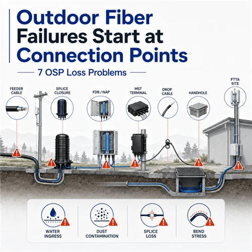
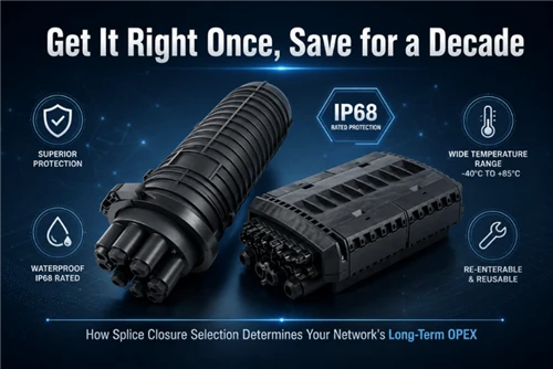
Store in a splice tray inside a fiber optic splice closure with an IP rating appropriate for the environment (IP67 minimum for outdoor)
Mechanical Splicing (Field-Expedient)
Use when a fusion splicer is unavailable. A v-groove aligns fibers with index-matching gel. Typical insertion loss: 0.1–0.3 dB - acceptable for short links but not for long cascaded runs. Follow the same strip/cleave/clean sequence as fusion.
Step 6: Terminate and Connect to Distribution Equipment
Termination creates the pluggable connector that plugs into optical network equipment.
Option A - Splice-on pigtail:
Factory-polished pigtail (LC/UPC or SC/APC are standard for FTTH) is fusion-spliced to the cable fiber in the field
Lowest insertion loss: typically < 0.3 dB total
Recommended for permanent infrastructure
Option B - Field-installable connector:
Pre-polished connectors with index-matching gel in the ferrule
Insertion loss: 0.3–0.5 dB typical - acceptable for drop cables
Faster installation; useful for service drops where speed matters
All connectors terminate at a fiber optic patch panel or ODF (Optical Distribution Frame), which provides organized, labeled access to every fiber. Use SC/APC (angled) connectors at the subscriber end to minimize reflectance (< -60 dB).
Step 7: Test Everything
Testing is not optional. An untested fiber network is an unknown fiber network. Run three tests in sequence:
Visual Fault Locator (VFL): Quick pass/fail continuity check. A 650 nm red laser shows light escaping at faults. Takes < 2 minutes per fiber.
Optical Loss Test Set (OLTS): Measures end-to-end insertion loss per TIA-526-7. Compare to your calculated link loss budget. Any fiber exceeding budget requires re-inspection of connectors and splices.
OTDR (Optical Time-Domain Reflectometer): Generates a detailed trace showing every event (connector, splice, bend, break) with its exact distance from the OTDR port. Save baseline traces - they are your reference for all future troubleshooting.
|
Typical FTTH Link Loss Budget (Example - 20 km PON) Cable loss: 20 km × 0.35 dB/km = 7.0 dB Connectors (4 × 0.3 dB) = 1.2 dB Splices (6 × 0.1 dB) = 0.6 dB PLC Splitter 1:32 = 17.0 dB Total: ~25.8 dB | Typical ONT budget: 28 dB | Margin: 2.2 dB ✓ |
Tools & Equipment Reference
|
Tool / Equipment |
Purpose |
Key Spec / Standard |
|
Fusion Splicer (auto-align) |
Permanent low-loss fiber joins |
Splice loss < 0.02 dB typical |
|
OTDR |
Fault location & splice quality |
Event dead zone < 1 m preferred |
|
Optical Loss Test Set (OLTS) |
End-to-end insertion loss |
Per TIA-526-7 / IEC 61280-4-2 |
|
Visual Fault Locator (VFL) |
Quick continuity check |
650 nm red laser, 5 mW min |
|
Fiber Cleaver |
Precise flat cleave for fusion |
Cleave angle < 0.5° |
|
Cable Tension Meter |
Pull force monitoring |
Never exceed 600 N |
|
Safety Glasses |
Laser & shard protection |
ANSI Z87.1 rated |
Safety Requirements - Non-Negotiable
Eye protection: ANSI Z87.1-rated safety glasses whenever fiber is stripped or laser sources are active. Invisible infrared laser (1310/1550 nm) can cause permanent retinal damage with zero sensation.
Cut-resistant gloves: Glass fiber shards (< 0.1 mm) are nearly invisible, penetrate skin easily, and are difficult to remove. Use level A4 cut-resistant gloves during cable handling.
Fall protection: Full-body harness + shock-absorbing lanyard meeting OSHA 1926.502 for all work above 6 feet. Inspect harness before every use.
Confined space: Telecom manholes are permit-required confined spaces. Test for oxygen deficiency and toxic gases (H₂S, CO) before entry. Continuous ventilation required.
Cable reel safety: Use cable reel jacks with spindle brakes. Align spindle horizontally, never vertically. An uncontrolled reel can weigh 500+ kg.
ESD protection: Wear a grounded wrist strap when handling optical transceivers and connectors. A single electrostatic discharge can destroy a connector end-face coating.
Fiber disposal: Collect all stripped fiber fragments in a sealed container labeled 'fiber waste.' Never leave fragments on work surfaces or floors.
Maintenance & Troubleshooting
Preventive Maintenance Schedule
Quarterly: Inspect outdoor splice closures and fiber pedestals for water ingress; check gasket condition
Annually: Run OTDR sweep of all backbone fibers; compare to baseline traces - any event that has grown by > 0.3 dB warrants investigation
As needed: Clean all connectors before every mating with IEC 61300-3-35 compliant tools and 99%+ IPA wipes
Common Fault Diagnosis
High loss at a connector: Dirty or damaged end-face. Clean and inspect with a 400× fiber microscope before replacing.
OTDR spike at a known splice location: Check for water entry into splice closure; verify heat-shrink sleeve integrity.
Gradual loss increase over months: Macro-bend developing in cable due to settlement or movement. Locate via OTDR; re-route or support cable.
Sudden complete loss: Physical break. Use OTDR to locate distance to fault; repair with mid-span fusion splice using a repair kit.
Loss correlated with temperature: Micro-bend from cable overtightened in clamp or tray. Loosen and re-route with proper bend radius.
Frequently Asked Questions
Q: What is the minimum bend radius for FTTH fiber optic cable?
A: During installation, maintain a minimum bend radius of 20 times the cable's outer diameter under load. After installation with no tension applied, this relaxes to 10 times the outer diameter. For G.657A2 bend-insensitive fiber in drop cables, the static minimum is 7.5 mm at the fiber level.
Q: What is the difference between SC/APC and SC/UPC connectors for FTTH?
A: SC/APC (Angled Physical Contact, green boot) has an 8° angled end-face that returns reflected light away from the fiber core, achieving < -60 dB return loss. It is the standard for FTTH subscriber-side connections where back-reflection degrades OLT performance. SC/UPC (Ultra Physical Contact, blue boot) delivers < -50 dB return loss and is used for equipment connections where high return loss is less critical.
Q: How deep should FTTH direct-buried cable be installed?
A: The industry standard (per TIA-590 and NEC Article 830) is 24 inches (610 mm) minimum under normal conditions, and 48 inches (1,220 mm) under driveways, parking lots, and roadways. Always consult local codes, as requirements vary by jurisdiction. Use 2 inches of bedding sand below and 4 inches above the cable before backfilling.
Q: Can I use a mechanical splice instead of fusion splicing for permanent FTTH infrastructure?
A: Mechanical splices are acceptable for temporary repairs and short drop cables, with typical loss of 0.1–0.3 dB per splice. For permanent passive optical network (PON) infrastructure, fusion splicing is strongly recommended: losses < 0.05 dB per splice preserve your link loss budget and prevent signal degradation over time, particularly important in 1:32 or 1:64 split PON architectures.
Q: How do I find a fiber break without an OTDR?
A: Use a Visual Fault Locator (VFL): the red laser light will visibly glow red at the break point or tight bend if the cable is accessible. For buried or concealed cables, an OTDR is the only practical tool for non-destructive distance-to-fault measurement.
About the Author
This guide was produced by the technical team at Ningbo Glory Optical Communication Co., Ltd., a fiber optic manufacturer established in 2009 and specializing in FTTH cable, splice closures, fiber patch cords, PLC splitters, and passive optical components. Our engineers hold FOA (Fiber Optic Association) certifications and have supported FTTH deployments across 40+ countries.
© 2026 Ningbo Glory Optical Communication Co., Ltd. | sales@gloryoptic.com | gloryoptics.com