Introduction: Why Your Fiber Patch Panel Choice Matters More Than Ever

As global fiber optic networks expand-driven by FTTH, 5G fronthaul, cloud data centers, and smart city initiatives-the physical layer has never been more critical. Market research indicates the global patch panels market is projected to nearly double over the next decade, with high-density fiber optical patch panels undergoing profound transformation due to shifting infrastructure paradigms.
At the heart of these networks sits an often-overlooked component: the fiber optic patch panel (also called an optical distribution frame, or ODF). This metal enclosure serves as the central hub for connecting and managing the physical aspects of fiber cables, distributing signals to the necessary parts of your network.
Choosing the right patch panel isn't just about counting ports-it's about building a foundation that balances density, flexibility, reliability, and future-readiness. This guide will help you make that decision with confidence.
Part 1: What Exactly Is a Fiber Optic Patch Panel?
A fiber optic patch panel is designed to mount in standard 19-inch, 21-inch, or 23-inch racks, with wall-mount options also available. Internally, it usually contains two distinct areas:
1.Adapter Panels – These hold the matrix of ports (adapters) to which cables are connected. The rear houses permanent connections (e.g., from incoming trunk cables), while the front provides accessible ports for temporary patching.
Splice Trays and Slack Storage – These areas allow splicing of incoming cables to pigtails and provide storage for excess fiber, preventing damage and maintaining proper bend radius.
How Does It Function?
The fiber optic patch panel excels at separating static and dynamic connections:
• Fixed side (internal ports): Connections from incoming cables (feeder or backbone) remain permanent, preserving the integrity of your core network infrastructure.
• Flexible side (external ports): Accessible ports on the panel's face accept short fiber patch cords, allowing easy reconfiguration without disturbing permanent cabling. This is essential for moves, adds, and changes (MACs).
Key Benefits
• Centralization of changes – All network connections are in one place, making modifications no longer a cumbersome process of tracing input ports through a rack.
• Less wear on expensive equipment – Routing connections through the patch panel minimizes wear and tear on valuable assets like servers or switches.
• Improved organization – Cables are kept neat and free from tangling, simplifying troubleshooting and enhancing airflow.
• Clear demarcation point – The panel creates a clear boundary between incoming service provider cables and your internal network.
Part 2: Fiber Patch Panel vs. Optical Distribution Frame (ODF) – What's the Difference?
Many people use these terms interchangeably, but there are important distinctions:
|
Feature |
Fiber Patch Panel |
Optical Distribution Frame (ODF) |
|
Typical size |
1U–4U, fits standard 19" racks |
Often a standalone cabinet or larger chassis |
|
Primary function |
Terminate and cross-connect fibers |
Terminate, splice, store, and distribute large fiber counts |
|
Splicing capability |
Limited (may have small splice tray) |
Built-in splice trays, often multiple cassettes |
|
Typical capacity |
12–144 fibers |
144–1,000+ fibers |
|
Environment |
Indoor, equipment rooms, data centers |
Central offices, headends, outdoor cabinets |
|
When to choose |
Rack-level distribution, LAN, small-medium networks |
High-density backbone, PON distribution, CO exits |
In short: a patch panel is ideal for rack‑level cross‑connects; an ODF is a patch panel on steroids for large‑scale fiber management.

Part 3: Key Factors to Consider When Choosing a Fiber Patch Panel
3.1 Port Count & Density
Start by assessing your current fiber count and projecting future growth. Common patch panel capacities include 12, 24, 48, 96, and even 144+ ports per panel.
• < 48 fibers: A wall‑mount or compact 1U rack‑mount panel often suffices.
• 48–144 fibers: Standard 1U or 2U rack‑mount panels are ideal.
• Hundreds to thousands of fibers: High‑density MPO‑based systems (e.g., 576 fibers in 4U) become necessary.
Pro Tip: Always leave 20–30% spare ports for future expansion. Network demands rarely decrease.
3.2 Loaded vs. Unloaded Panels
|
|
Loaded Panels |
Unloaded (Empty) Panels |
|
Adapters included? |
Yes, pre-installed |
No, you buy separately |
|
Flexibility |
Low (fixed connector type) |
High (mix SC, LC, FC on same panel) |
|
Typical use |
Standardized deployments |
Custom networks, mixed environments |
|
Initial cost |
Higher upfront |
Lower upfront (plus adapters) |
Recommendation: For multi-tenant buildings or networks with evolving needs, unloaded panels offer better long-term flexibility.
3.3 Connector Types & Polishing (UPC vs. APC)
Your patch panel must be compatible with the transceivers and patch cords used in your network.
|
Connector |
Ferrule size |
Typical density |
Common use |
|
LC |
1.25mm |
Very high |
Data centers, 10G/25G/100G |
|
SC |
2.5mm |
Moderate |
Telecom, FTTH, GPON |
|
FC |
2.5mm (threaded) |
Low |
High-vibration environments |
|
ST |
2.5mm (bayonet) |
Low |
Legacy networks |
|
MTP/MPO |
Multi-fiber (8–24+ fibers) |
Ultra-high |
40G/100G/400G backbone |
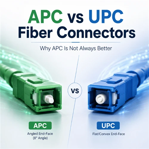
UPC vs. APC Polishing
• UPC (Ultra Physical Contact) – Blue connectors, return loss ≥50dB. Suitable for most data communications.
• APC (Angled Physical Contact) – Green connectors, return loss ≥60dB. Essential for PON (GPON, EPON, XGS‑PON) and analog video transmission to prevent signal reflections.
A single MTP/MPO cord can replace 12–24 duplex LC pairs, reducing rack space by up to 75%.
3.4 Form Factor: Rack Unit Height
|
Height |
Typical fiber count |
Best for |
|
1U (1.75") |
12–48 fibers (LC), up to 96 fibers (MPO) |
Data center top-of-rack, small telecom rooms |
|
2U (3.5") |
48–96 fibers |
Larger cross-connect fields, central offices |
|
4U (7") |
144–576+ fibers |
High-density core distribution |
3.5 Enclosure Access: Fixed vs. Sliding vs. Drawer
|
Design |
Access to rear |
Maintenance ease |
Cost |
|
Fixed / removable lid |
Difficult (must remove panel) |
Low |
Lowest |
|
Sliding / pivoting |
Pulls forward, no de-mounting |
High |
Moderate |
|
Drawer / cassette |
Full extension, front access |
Very high |
Highest |
Recommendation: For networks with frequent changes (MACs) or tight rack spaces, invest in sliding or drawer designs. They can reduce maintenance time by up to 50%.
3.6 Material & Build Quality
Look for panels manufactured from high‑quality cold‑rolled steel with electrostatic powder coating for corrosion resistance and long‑term stability. Key quality indicators:
• Thickness – ≥1.2mm for load‑bearing parts
• Finish – Uniform, scratch‑resistant
• Grounding – Built‑in grounding studs for metallic cable shielding
• Flame rating – UL 94 V‑0 or UL 94 HB
3.7 Standards & Performance
Ensure your panel meets relevant standards:
• TIA/EIA-568 (structured cabling)
• ISO/IEC 11801 (international cabling)
• GR-326-CORE (Telcordia connector requirements)
• IEC 61754 (connector interfaces)
Typical optical performance specifications (single-mode):
• Insertion loss: ≤0.2dB (adapter only)
• Return loss: ≥50dB (UPC) or ≥60dB (APC)
• Durability: ≥500 mating cycles
• Operating temperature: -40°C to +85°C
Part 4: Comparing Three Representative GLORY Patch Panel Types
To illustrate how different designs serve different needs, here are three GLORY patch panels covering low-density fixed, sliding ODF, and high-density MPO configurations.
4.1 GL-JPF Series (1U/2U Slide-Out Patch Panel)

Best for: General telecom, LAN, and access networks where easy front access is important.
|
Specification |
Details |
|
Form factor |
19″ 1U (24–48 fibers) or 2U (48 fibers) |
|
Adapter support |
SC, FC, ST, SC Duplex (field-replaceable panels) |
|
Key feature |
Slide-out drawer on precision ball-bearing rails |
|
Cable entry |
Φ8–16mm (1U) or Φ8–25mm (2U), nut squeeze sealing |
|
Material |
Cold-rolled steel, anti-corrosion coating |
Why choose this: The slide-out design lets you access rear connections without removing the panel from the rack – a huge time-saver during maintenance and reconfiguration.
4.2 SC APC Patch Panel (1U or Wall-mount)
Best for: FTTH ODN nodes, PON networks, and small central offices needing excellent return loss.
|
Specification |
Details |
|
Form factor |
19″ 1U (24 cores) or wall-mount |
|
Adapters |
Pre-loaded SC/APC (green) |
|
Key feature |
Return loss ≥60dB, sliding tray for easy splicing |
|
Splice capacity |
Up to 24 pigtails (splice tray built-in) |
|
Bend radius guarantee |
≥37.5mm |
Why choose this: SC/APC is the de-facto standard for GPON/XGS-PON drop networks. The built-in splice tray and sliding design make it a complete ODF-lite for FTTx distribution points.

4.3 High-Density MPO Patch Panel (4U, 576 Fibers)

Best for: Hyper-scale data centers, cloud providers, and central offices facing 400G/800G migration.
|
Specification |
Details |
|
Form factor |
19″ 4U |
|
Max capacity |
576 fibers (48 MPO cassettes, 12 fibers each) |
|
Cassette type |
Pre-terminated MTP/MPO to LC (or MPO to MPO) |
|
Key feature |
Factory-terminated, plug-and-play, sliding trays |
|
Polarity |
Type A/B/C cassettes selectable |
Why choose this: Each MPO trunk replaces 12 duplex LC jumpers. The 4U height packs 576 fibers – a 75% space saving compared to traditional LC panels. Pre-terminated cassettes reduce on-site installation time by over 80%.
Part 5: Common Mistakes to Avoid
1.Underestimating future growth – A panel that is 100% full today will be a problem tomorrow. Always reserve spare ports.
2.Ignoring bend radius – Cramming cables into a panel without proper slack storage can cause micro-bends and signal loss. Look for panels with ≥37.5mm bend radius control.
3.Mixing UPC and APC – Using a blue (UPC) patch cord in a green (APC) adapter damages the ferrule. Ensure your panel's adapter color matches your patch cord connector color.
4.Choosing fixed panels for high‑change environments – If you frequently reconfigure ports, the extra cost of sliding/drawer panels pays back quickly in labour savings.
5.Forgetting cable management – A patch panel without horizontal or vertical cable managers leads to messy, impossible‑to-trace spaghetti. Budget for management bars or rings.
Part 6: Future Trends – What to Look for in 2026 and Beyond
• VSFF connectors – Very Small Form Factor (CS, SN, MDC) allow even higher density (up to 1,728 fibers in 1U). Ensure your panel can accept adapter plates for these new interfaces.
• MPO migration to 400G/800G – Panels must support 16-fiber (MPO-16) and 24-fiber (MPO-24) configurations as higher-speed optics emerge.
• Pre-terminated modular systems – Factory-terminated cassettes reduce on-site termination errors and speed deployment. This trend will continue.
• AI-driven data center expansion – AI clusters require massive fiber counts and reconfigurability. Panels with modular, scalable architectures will be essential.
• Smart patch panels – Some vendors now offer panels with RFID or LED port-tracking to guide technicians. While still niche, this technology will mature.
Conclusion: Make the Right Choice for Your Network
The fiber optic patch panel you choose today will impact your network's reliability, scalability, and operational efficiency for years to come. By carefully evaluating your port count, density needs, access preferences, connector types, and future growth plans, you can select a patch panel that serves as a rock-solid foundation for your infrastructure.
GLORY Optical offers a range of patch panels – from simple fixed 1U units to high-density 4U MPO systems and slide-out ODFs – each designed for specific network tiers. With 18 years of manufacturing experience, ISO 9001 certification, and a 3-year warranty, GLORY provides the reliability, density, and future-readiness your network demands.