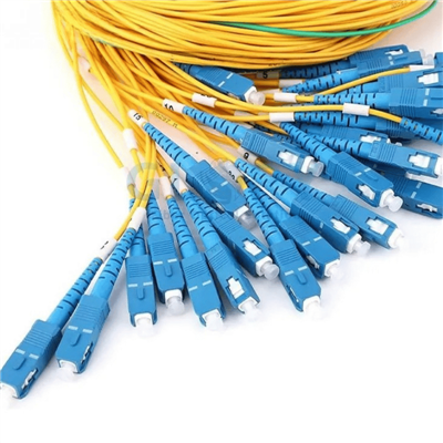
Product overview
A Parallel-Fiber Splitter Assembly, Not a Conventional Fan-Out Pigtail
This product combines passive optical power division with MPO/MTP multi-fiber connectivity. Its commercial value is not simply "more fibers in one connector"; the main design task is preserving the intended relationship between optical split, physical connector orientation, channel numbering, and the equipment or panel receiving each branch.
Project value
Where the MPO/MTP Splitter Changes the BOM
The assembly is most useful when a project already uses parallel-fiber interfaces and needs passive optical division without converting every channel to individual simplex connectors.
Multi-Fiber Ports Reduce Front-Panel Occupancy
MPO/MTP interfaces carry multiple fibers through one connector body. Compared with a design that terminates every branch on separate SC or LC adapters, the cassette can reduce adapter count and patch-panel face consumption. The exact density benefit depends on the selected fiber count, connector keying and receiving cassette.
Passive Division and Connectorization Arrive as One Assembly
The splitter module, pigtails and multi-fiber connectors are delivered as one project-defined unit. This avoids sourcing a loose PLC device and a separate MPO harness, but it also means that connector gender, pin state, polarity and channel assignment must be frozen before production rather than corrected casually in the field.
MPO/APC Endface Listed for the Product
The original specification identifies an MPO/APC ferrule endface. An angled interface is relevant where reflected optical power must be controlled, but the mated adapter, mating connector and active equipment must use the same compatible interface. MPO/APC must not be treated as interchangeable with an MPO/UPC connection.
Published Dual-Window Operation
The source page lists operation at 1310 and 1550 nm, with polarization-dependent loss of no more than 0.15 dB and directivity of at least 55 dB. These values support quotation-stage comparison; the final acceptance sheet should still identify the actual test wavelengths and per-channel limits for the ordered assembly.
Cassette Housing Organizes the Optical Circuit
The photographed black cassette groups the splitter circuit and fiber transitions into a defined module rather than leaving a bare chip and loose fibers exposed inside a panel. The buyer should confirm the cassette envelope, mounting points and exit direction because the source page does not publish dimensional drawings.
Channel Mapping Can Be Documented Before Shipment
Parallel-fiber assemblies can fail functionally even when every fiber passes light. A project BOM should therefore include channel numbering, input-to-output mapping, polarity method, connector orientation and label text. Glory Optical can use the approved drawing as the production reference for assembly, labeling and batch inspection.
Configuration control
Separate Published Features from Order-Specific Decisions
The page below distinguishes what is explicitly stated on the supplied product page from items that still require a drawing or quotation confirmation.
| Configuration field | Published information | What the buyer must confirm |
|---|---|---|
| Product family | ABS PLC splitter / cassette-style fibre splitter | Final housing envelope, mounting method and panel compatibility |
| Split architecture | 1×4 PLC fibre splitter | Whether the project uses one 1×4 circuit or a multi-channel 12×1:4 architecture shown on the photographed label |
| Transmission medium | Single-mode | Fiber standard, cable construction and required jacket marking |
| Connector family | MPO/MTP | MPO or MTP brand requirement, fiber count, male/female, pinned/unpinned, key orientation and adapter type |
| Endface | MPO/APC | Mating interface and acceptance criteria for endface inspection |
| Fiber outputs | Source text mentions 12 colored pigtails and 0.25 or 0.9 mm fiber options | Actual pigtail count, buffer diameter, color sequence, cable length and branch identification |
| Application interfaces | Fiber distribution frame, network equipment, fiber module and CATV/LAN are listed | Exact receiving equipment, available optical budget and whether passive power division is supported by the link design |
Published technical data
General and Optical Specifications
Only values stated on the supplied product page are shown as fixed data. Unpublished dimensions, weight, IP/IK rating, tensile strength and connector insertion loss are not inferred.
General specification
| Parameter | Published value |
|---|---|
| Listed model | 1×4 PLC Fiber Optic Splitter – FTTH Single Mode 2.0 mm Cassette MPO/MTP Connector |
| Product type | Passive optical fibre splitter |
| Transmission medium | Single-mode |
| Structure | MPO |
| Ferrule endface | MPO/APC |
| Fabrication process | Coupling, as listed on the source page |
| Operating temperature | −40 to +85 °C |
| Storage temperature | −40 to +85 °C |
Optical specification
| Parameter | Published value |
|---|---|
| Operating wavelength | 1310 and 1550 nm |
| Operating bandwidth | 1310/1550 ±40 nm, as listed in the source reference table |
| Polarization-dependent loss | ≤0.15 dB in the product summary |
| Temperature-dependent loss | ≤0.2 dB in the source reference table |
| Directivity | ≥55 dB |
| Return loss | ≥55 dB in the source reference table |
| 1×4 worst-port insertion loss | Confirm by datasheet Not published as a 1×4 PLC value on the supplied page |
Original product photography
Module and Connector Views
All product photographs below are extracted from the supplied product page and embedded in this file. No connector, port or enclosure structure has been redrawn.


Optical architecture
How the Splitter Circuit and MPO/MTP Interface Relate
The source diagrams show both the PLC signal path and the connector/application context. They are included as configuration aids, not as a substitute for a model-specific production drawing.

Published splitter structure diagram: input fiber, fiber array, splitter chip, output array, adhesive and output ribbons.

Published connector illustration. The final assembly must use the ordered endface, gender, key and pin configuration.

Source-page application diagram. Passive optical splitting must be supported by the optical link budget and cannot replace an active Ethernet switch.
Application scenarios
MPO/MTP Fibre Splitter Applications Requiring Controlled Channel Mapping
These scenarios focus on where the connectorized assembly can be integrated and which project details must be settled before purchase.
High-Density ODF or MPO Patch-Panel Integration
A panel designed around simplex adapters can consume substantial face space when a passive split must be presented across multiple parallel channels. The cassette-style splitter consolidates the optical circuit behind MPO/MTP interfaces and can be integrated near a high-density ODF or MPO panel. Before procurement, confirm panel clearance, module fixing points, connector access direction, MPO gender, pin state, polarity and the exact channel sequence expected at the receiving cassette.
Optical Monitoring and Specialty Signal Distribution
Some test, monitoring, CATV or specialty optical systems require one optical path to be divided passively across several receivers. This module can place the split and multi-fiber interconnect in one assembly, avoiding a field-built combination of loose splitter and harness. The buyer must verify receiver sensitivity, total optical budget, operating wavelength, permissible branch imbalance and whether the equipment supports passive power division. It does not copy Ethernet traffic or provide switching functions.
OEM Integration into Network Equipment or Fiber Modules
A loose PLC component may not match the mechanical or connector architecture of proprietary equipment. The cassette assembly provides a defined housing and MPO/MTP exits that can be incorporated into an OEM chassis, fiber module or distribution frame. The quotation package should include an equipment drawing, available module envelope, bend-control area, cable exit orientation, connector mating specification, label convention and acceptance test format so the delivered assembly matches the final BOM.
Project configuration
OEM Assembly Based on an Approved Interface Drawing
The source page does not present every photographed arrangement as a universal standard model. A controlled order therefore begins with a configuration sheet rather than a generic request for "one MPO splitter."
Company background
Why Glory Optical for Connectorized Splitter Projects
Glory Optical was founded in 2008 and is headquartered in Ningbo, China. Its current product portfolio covers passive optical splitters, MPO/MTP assemblies, fiber boxes, optical cable and connection components, allowing the splitter circuit and multi-fiber interface to be reviewed as one project BOM rather than as unrelated purchases.
Splitter and Cable-Assembly Coordination
Glory Optical lists splitter processing, fiber cable production and connector assembly within its manufacturing scope. For this product, that supports coordinated confirmation of the PLC circuit, MPO/MTP interfaces, pigtail construction and labeling before batch assembly.
Drawing-Based OEM/ODM Support
The company provides OEM/ODM services that include product configuration, labeling and packaging. A project can therefore use an approved interface drawing and channel map as the basis for production instead of depending on a generic catalogue description.
Optical Testing and Batch Documentation
Project testing can be specified around the ordered assembly: per-channel insertion loss, return loss, polarity or continuity checks, and batch identification. The exact report format and limits should be agreed before production because the supplied product page does not publish a complete 1×4 acceptance sheet.
Send the Split Ratio and MPO/MTP Channel Map Together
For an accurate quotation, provide the required circuit count, input and output connector definitions, polarity, channel mapping, pigtail construction, cassette envelope and optical acceptance limits. Glory Optical can review the combined optical and mechanical configuration before production.
Hot Tags: mpo/mtp 1×4 fiber splitter, China mpo/mtp 1×4 fiber splitter manufacturers, suppliers, factory, 1x2 Plc Splitter, fiber cable splitter, fiber optic splitter, passive optical network splitter, Splitter Cassette, Splitter Plc 1x8