


What Is an FPV Drone Fiber Optic Cable System?
An FPV drone fiber system replaces the primary radio-based video and control link with a physical optical connection. A typical system contains a ground-side transceiver, single-mode optical fiber, a drone-mounted payout spool and an airborne transceiver connected to the drone electronics.
The electrical data is converted into optical signals at one end, transmitted through the fiber and converted back into electrical data at the other end. Two-way systems perform the same conversion in both directions.
Drone-Mounted Spools and Ground Tethers Are Different Systems
| System type | Spool location | Primary purpose | Qualification focus |
|---|---|---|---|
| Drone-mounted payout spool | On the UAV | Control, video and sensor data | Payload mass, payout behavior, abrasion and available fiber length |
| Ground-based data tether | At the ground station | Continuous optical data link | Tether drag, tension management and repeated retrieval |
| Hybrid power-and-data tether | Normally at the ground station | Electrical power plus optical data | Conductor mass, voltage, heating, drag and optical performance |
This guide focuses primarily on drone-mounted payout spools. Specifications from a hybrid power tether should not be applied to an ultra-light FPV reel without reviewing the complete construction.
How the Optical Fiber Is Constructed
The center of an optical fiber is a glass core that carries the light signal. A surrounding cladding layer has a different refractive index, allowing light to remain guided along the core. Protective coatings are applied because bare glass is vulnerable to abrasion, surface damage and excessive bending.
The finished construction varies by application. An ultra-light drone fiber may use a primary coating, resin or nano-coating, or additional aramid reinforcement. It should not automatically be described as a conventional TPU- or PVC-jacketed telecom cable.
Aramid fibers such as Kevlar are widely used as optical-cable strength members, but they are one design option rather than a universal feature. Their purpose is to carry tensile load and limit strain on the glass fiber. DuPont provides a useful technical overview of Kevlar in fiber optic cable construction.
Why Bend-Insensitive Single-Mode Fiber Is Common
Compact spools expose fiber to smaller winding radii than many conventional installations. For this reason, many drone systems specify G.657.A2 bend-insensitive single-mode fiber. ITU-T G.657 defines fibers with improved macrobending performance compared with conventional G.652 fiber.
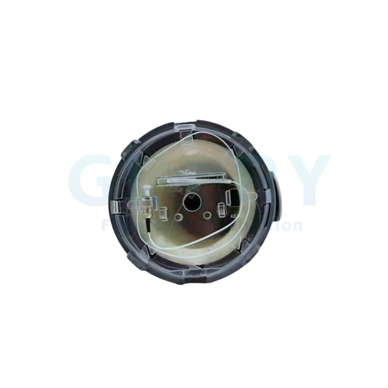
Internal spool view. Winding geometry, fiber path and the transition to the exit port must be evaluated together; the fiber grade alone does not determine payout reliability.
How the Optical Signal Travels
The drone camera, controller or sensor system produces electrical data. The airborne transceiver converts that data into modulated light, which travels through the fiber to the ground-side transceiver. The ground unit converts the optical signal back into electrical data for the control station.
The fiber can support high data rates, but usable bandwidth is determined by the complete link. Transceiver capacity, protocol, optical power budget, attenuation, connector loss, encoder performance and processing latency must all be considered.
The optical path is not affected by conventional RF interference because the information travels as light. This does not make every drone subsystem immune to disruption. Navigation receivers, power electronics, onboard computers and optical transceivers remain separate components with their own risks.
Why Spool Design Matters as Much as Fiber Selection
During flight, the fiber passes through an exit port while the drone changes speed, direction and altitude. Poor reel geometry or uncontrolled payout can create sudden tension, slack, entanglement, excessive bending and repeated contact with a sharp edge.
The exit port is a critical wear point because moving fiber repeatedly contacts a small surface area under tension. A spool may pass a short inspection yet develop damage after repeated use. Optical loss can increase before the coating damage or glass fracture becomes visible.
Internal Case: Wear at an Unprotected Exit Port
During a limited internal comparison, the Glory Optical engineering team evaluated three third-party plastic spool assemblies without a reinforced cable exit. The observed sequence was consistent: the fiber contacted the edge of the opening, a groove formed in the plastic, continued wear produced a damaged edge, and the edge began abrading the fiber surface.
This was an internal design comparison, not an industry-wide failure-rate study. It supports inspection of exit-port materials and geometry, but it does not prove that every plastic spool will fail in the same way.

Ceramic exit insert used in a Glory Optical assembly. A polished insert can provide a more wear-resistant contact surface than an unreinforced plastic opening. Material grade, finish, edge radius and alignment still require verification.
What a Ceramic Exit Insert Can and Cannot Do
A properly specified ceramic insert can reduce localized wear and provide a smoother surface as the fiber changes direction. Its performance depends on ceramic material, hardness, surface finish, edge radius, alignment, bonding method, contact angle and payout tension.
It cannot compensate for poor winding geometry, excessive tension, contamination or a fiber path that violates the minimum bend radius. It should be evaluated as one component of the complete spool design.
Recommended Product Paths
Select the system architecture before comparing cable length or reel weight. The following Glory Optical products represent two different operating models rather than interchangeable versions of the same product.

GL-FPV Drone-Mounted Payout Spool
For UAV projects that need a compact reel carried by the aircraft. The supplier page lists G.657.A2 single-mode fiber, 0.27–0.4 mm fiber options and standard reel lengths from 3 km to 30 km.
Verify before purchase: exact reel mass, payout tension, transceiver configuration, connector loss and environmental test conditions for the selected length.

GL09-GXT Inner-Winding Reusable System
For projects that require a controlled deployment-and-retrieval architecture. The supplier page lists nano-coated, resin-coated and Kevlar-reinforced G.657.A2 fiber configurations.
Verify before purchase: retrieval method, applicable cable length, tensile rating, cycle-test procedure and suitability for the actual terrain and UAV platform.
Evidence type: Supplier-published product information. Product configuration and test reports should be confirmed for the specific order.
Specifications to Check Before Selecting a Drone Fiber Spool
| Specification | Why it matters | What to request |
|---|---|---|
| Fiber type | Influences bending loss and link compatibility. | Fiber standard, manufacturer and reason for selection. |
| Finished fiber diameter | Affects reel volume, mass and mechanical protection. | Clarify whether the value describes coated, reinforced or complete cable diameter. |
| Optical attenuation | Determines part of the end-to-end power budget. | dB/km at each operating wavelength plus connector and splice limits. |
| Minimum bend radius | Small bends can increase loss and reduce mechanical life. | Static and dynamic limits for the finished fiber assembly. |
| Tensile strength | Defines the maximum load before damage or failure. | Test method, sample length, loading rate and failure criterion. |
| Payout tension | Controls slack, shock loading and fiber stability. | Normal and peak values across the rated payout speed. |
| Total module mass | Directly affects UAV payload and endurance. | Mass of the selected length including housing, connectors and transceiver. |
| Exit-port design | Can become a localized abrasion and bending point. | Material, edge radius, alignment and wear-test procedure. |
| Environmental limits | Coatings, adhesives and electronics may have different limits. | Test data for the complete assembly, not only a resin or fiber datasheet. |
Benefits and Limitations of an FPV Fiber Link
Potential Benefits
- Resistance to RF interference on the optical communication path;
- Low signal attenuation over long distances;
- High data capacity when matched with suitable transceivers;
- No RF radiation from the fiber itself;
- A physical data path where wireless links are unreliable.
Important Limitations
- Range is limited by available fiber length;
- The fiber can snag, bend, abrade or break;
- The spool adds payload mass;
- Connectors and transceivers remain failure points;
- Navigation and other radio-dependent systems may still be disrupted.
Fiber is generally lighter than a copper data cable designed for comparable long-distance bandwidth, but a meaningful comparison must define the conductor type, distance, data rate, shielding and whether electrical power delivery is included.
Physical access to the fiber is normally required for interception or direct disruption, making passive over-the-air interception more difficult than with a radio link. This should not be described as absolute protection against tapping, sabotage or endpoint compromise.
Practical Supplier Qualification Checklist
Before approving a fiber optic drone spool, request evidence for the exact configuration being purchased:
- Fiber manufacturer, grade and finished construction;
- Attenuation at the operating wavelengths;
- Static and dynamic bend limits;
- Tensile test method and payout-tension range;
- Reel mass for the required fiber length;
- Exit-port material, geometry and abrasion test;
- Connector insertion-loss and return-loss limits;
- Transceiver bandwidth, protocol and measured latency;
- Environmental test conditions for the complete assembly;
- Deployment, retrieval and inspection procedure;
- Batch traceability and warranty criteria.
FPV Drone Fiber Optic Cable FAQ
Q: Is an FPV drone fiber optic cable immune to jamming?
A: The optical communication path is not affected by conventional RF jamming because the data travels as light inside the fiber. Other subsystems, including navigation receivers and electronic equipment, may still be affected by interference or attack.
Q: Does the fiber spool sit on the drone or on the ground?
A: In many FPV systems, the spool is mounted on the drone and pays out fiber during flight. In conventional tethered UAV systems, the reel is normally managed from the ground. The two architectures have different mass, tension and retrieval requirements.
Q: Can the fiber be reused?
A: Some systems are intended for one-way payout, while others support controlled retrieval. Reusability depends on coating construction, terrain, bending history, abrasion, spool mechanics and the post-flight inspection procedure.
Q: Why is G.657.A2 fiber used in compact drone spools?
A: G.657.A2 fiber is designed for improved macrobending performance at small bend radii. It is therefore a common candidate for compact winding, although the complete spool still requires dynamic mechanical and environmental qualification.
Q: Does a ceramic exit insert prevent every fiber failure?
A: No. It can reduce wear at one contact point, but it cannot prevent failure caused by excessive tension, poor winding, contamination, severe bending, connector damage or snagging.
Q: What matters more: the fiber or the spool?
A: Both matter. The fiber determines optical and part of the mechanical performance, while the spool controls storage and deployment. A weakness in either component can interrupt the link.
Final Takeaway
A drone fiber optic cable should be evaluated as a complete communication and deployment system, not simply as a strand of glass. Fiber grade, coating, winding geometry, payout tension, exit-port design, connectors, transceivers and operating conditions all contribute to reliability.
The most credible supplier should be able to explain how these components work together and provide test conditions for its key performance claims. For available configurations, review Glory Optical's FPV drone fiber optic cable systems or request a technical datasheet for the required UAV platform and cable length.





