What determines whether an optical splitter performs reliably?
The split ratio is only the starting point. A reliable splitter must keep maximum insertion loss within the link budget, distribute power consistently across its outputs, limit reflected light and maintain adequate isolation. Packaging, connectors, fiber type and test conditions must also match the installation.
Optical splitters are passive components used to divide one input light signal into multiple output paths. In FTTH, GPON and EPON networks, they allow one feeder fiber to serve multiple subscribers without installing powered equipment at every distribution point.
However, selecting a splitter only by a label such as 1×8, 1×16 or 1×32 does not confirm that the complete optical path will be stable. The same nominal configuration can deliver different field results when insertion loss, port-to-port variation, reflection, connector quality or packaging are not controlled.
Limitations of Selecting Optical Splitters by Split Ratio Alone
Optical Power Budget Challenges
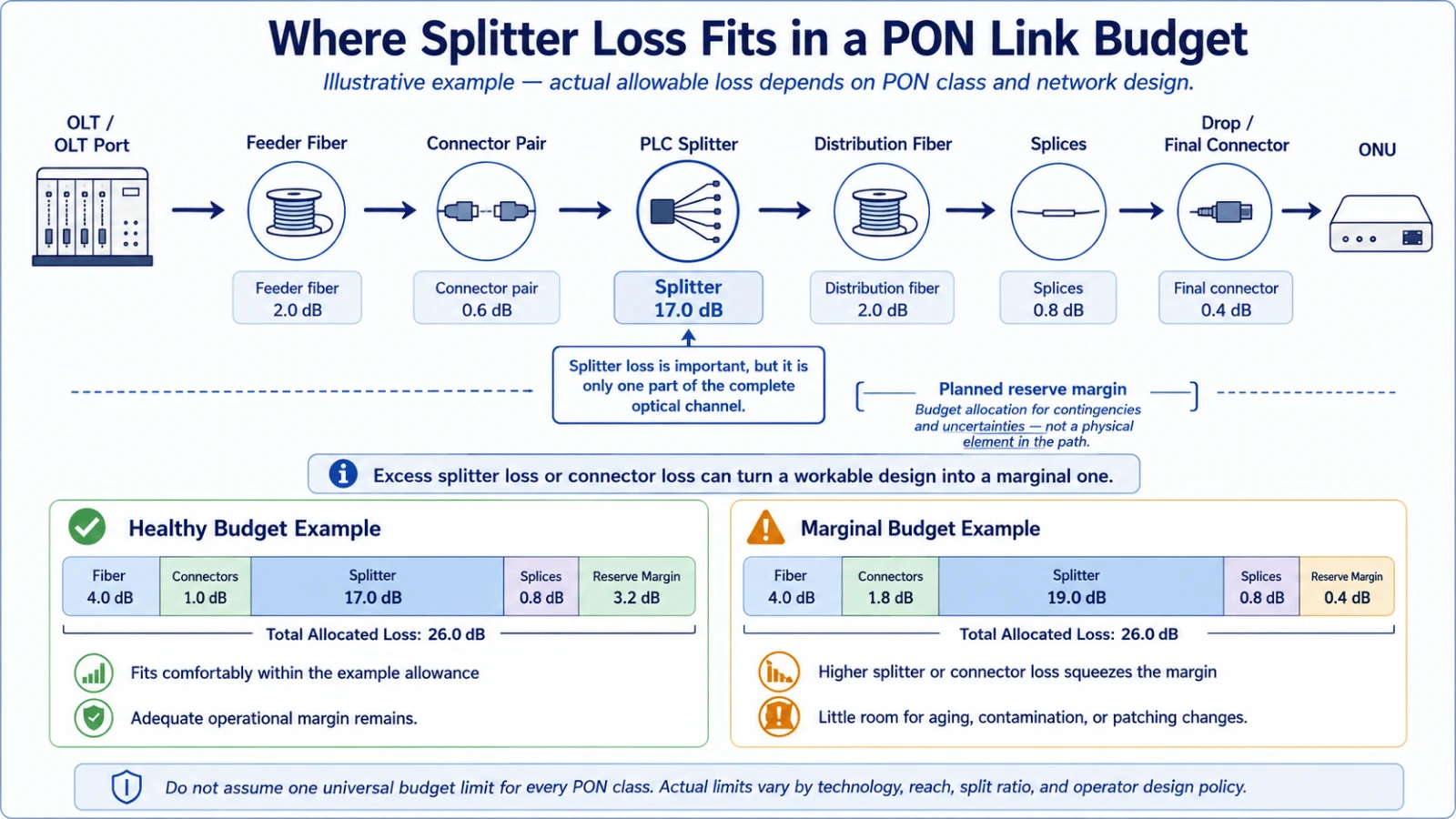
Every optical split reduces the power available at each output. Higher split ratios therefore consume a larger portion of the OLT-to-ONU loss budget before fiber attenuation, connectors, splices and engineering margin are added.
If the actual insertion loss is higher than the design value, the farthest or most heavily connected subscriber path may approach the receiver limit. A network can appear acceptable during initial activation but become less tolerant of dirty connectors, extra repair splices or future route changes.
Output Consistency Challenges
A splitter can meet its nominal configuration while producing uneven output power. When port-to-port variation is too large, some ONU paths retain comfortable margin while others operate closer to the receiver threshold.
This matters in networks where route lengths are already unequal. A weak splitter output combined with the longest distribution fiber can create a difficult-to-maintain worst-case path. For equal-distribution PON designs, buyers should therefore review both maximum insertion loss and output uniformity.
Reflection and Signal Isolation Challenges
Reflected optical power can return toward the source when light encounters discontinuities at connectors, splices or component interfaces. Poor isolation can also allow unwanted optical interaction between paths in applications that use passive tapping, monitoring or multiple signal directions.
These issues may not create an immediate outage, but they can reduce system tolerance and make troubleshooting more complex. Connector polish, ferrule condition and end-face cleanliness remain part of the final result, even when the internal splitter element is within specification.
Key Performance Indicators of Optical Splitters
Lower Insertion Loss Preserves Usable Optical Margin
Insertion loss describes the optical power reduction between the input and a selected output port. The relevant procurement value is normally the maximum allowed loss across all required wavelengths and ports-not only a typical laboratory value.
When evaluating a PLC splitter, include the splitter loss in the complete channel calculation. Connectorized modules should be evaluated as complete assemblies because the connectors and pigtails contribute to the measured result.
Ask whether the stated insertion loss is typical or maximum, whether connector loss is included, which wavelengths were tested and whether the report identifies the worst output port.
Stable Splitting Ratio and Uniformity Make Planning Predictable
The splitting ratio defines how input power is distributed. In standard FTTH networks, PLC technology is commonly used when equal power distribution is required across multiple outputs. Uniformity then indicates how closely those outputs match one another.
A 1×8 PLC splitter, for example, may fit a lower-density distribution point where the optical design favors more margin per branch. Higher port-count products such as a 1×32 fiber splitter module serve more endpoints but require a tighter review of the complete optical budget.

Higher Return Loss Reduces Reflected Optical Power
Return loss indicates how much light is reflected back toward the source. A higher return loss value means less optical power is being reflected. The value should be considered together with connector type, polish and end-face condition.
Return loss is especially relevant where reflection sensitivity is higher or where several connectorized components are placed in series. A clean test result at the component level does not remove the need to inspect and clean connectors before final installation.
Adequate Isolation Limits Unwanted Path Interaction
Isolation describes the ability of a passive component to limit unwanted optical energy between paths. It is particularly relevant for couplers used in monitoring, bidirectional transmission, sensing or specialty optical systems.
For these applications, a general splitter specification may be insufficient. The operating wavelength, direction of transmission, required coupling ratio and isolation requirement should be stated in the RFQ.
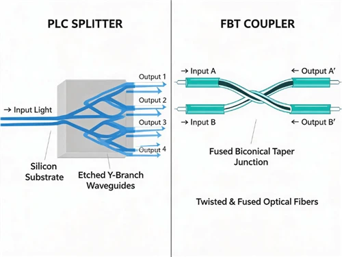
PLC Splitter or FBT Coupler?
PLC and FBT devices both distribute optical power, but they are not interchangeable in every project.
| Selection Point | PLC Splitter | FBT Coupler |
|---|---|---|
| Typical role | Equal distribution in FTTH, GPON, EPON and passive optical LANs | Low-port-count coupling, monitoring, tapping and specialty optical paths |
| Power distribution | Commonly equal across standard output counts | Can be configured with unequal ratios such as a main path and monitoring tap |
| Port-count fit | Well suited to standard higher-count PON configurations | Often selected for 1×2 or 2×2 applications |
| Selection risk | Ignoring maximum loss, uniformity or package constraints | Ignoring wavelength dependence, directionality or custom ratio tolerance |
For equal-distribution access networks, begin with the Glory Optical PLC splitter range. For custom low-count or unequal-ratio applications, review the optical fiber coupler range.
Glory Optical Splitter Product Options
Glory Optical provides splitter assemblies in multiple technologies and package formats. The correct product should be selected from the installation environment and test requirements rather than from port count alone.
Recommended Splitter Products by Application
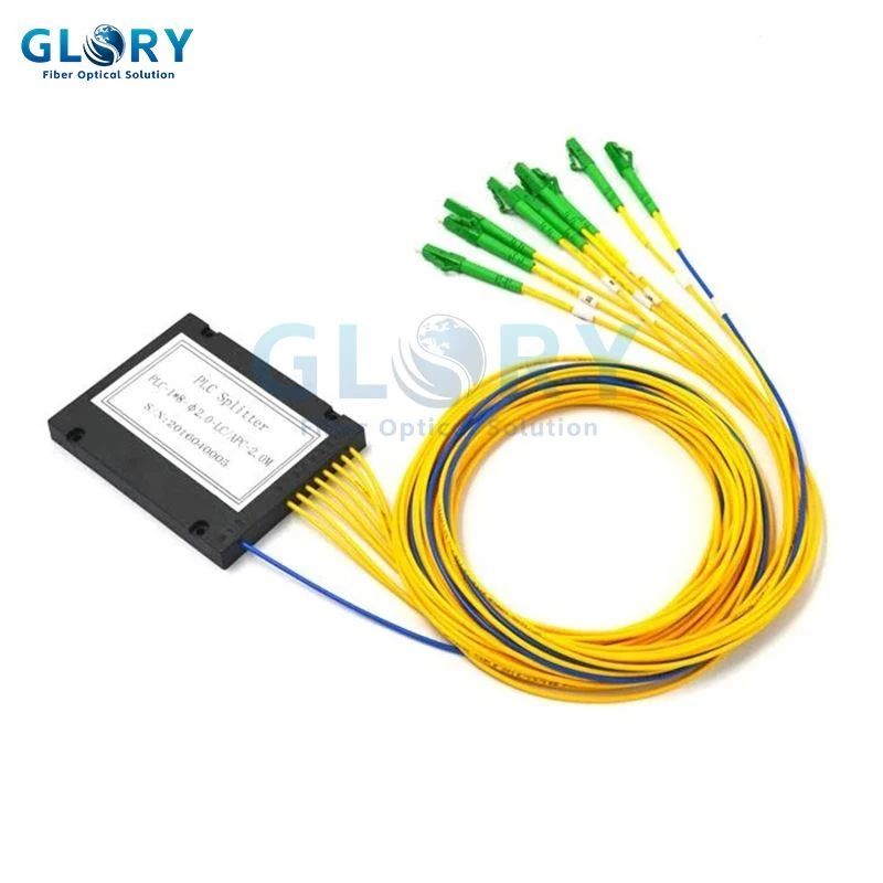
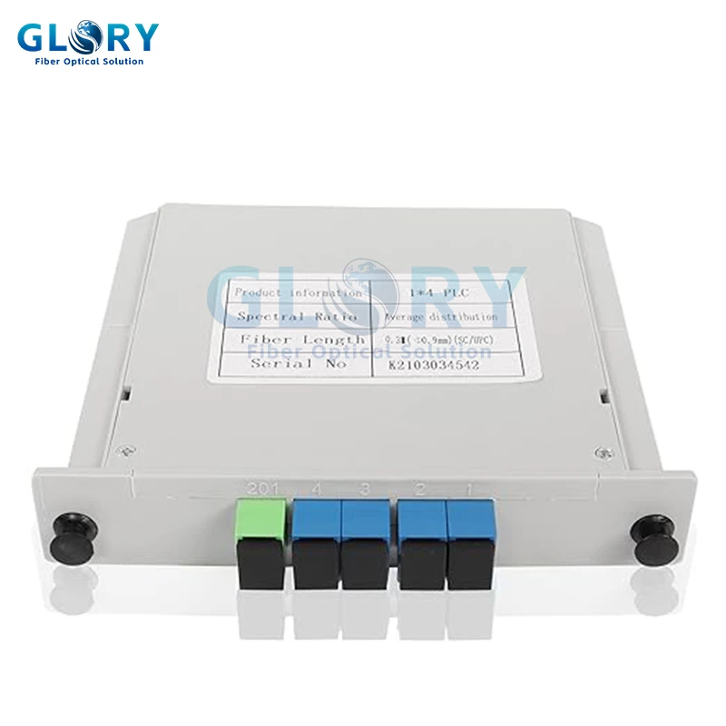
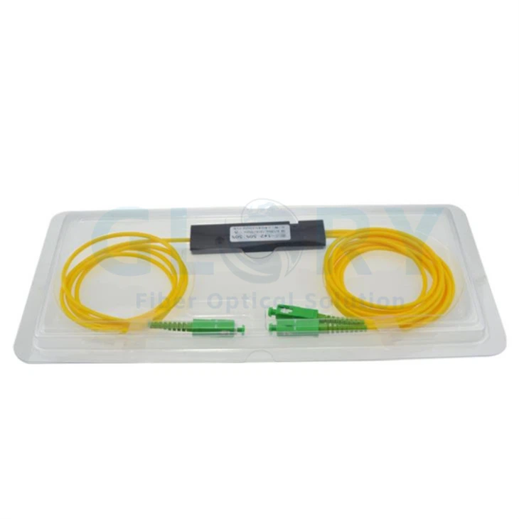
These products cover four common selection paths: compact low-count branching, standard FTTH distribution, modular panel installation and custom low-count coupling.

| Requirement | Relevant Glory Product | Typical Use |
|---|---|---|
| Complete splitter range | Fiber Optic Splitters | Compare PLC splitters, FBT couplers and available package formats |
| Compact low-count PLC assembly | PLC Splitter 1×2 | Small distribution nodes, compact boxes and low-count branching |
| Common FTTH distribution ratio | PLC Splitter 1×8 | FTTH distribution points where coverage and optical margin must be balanced |
| Modular panel installation | Splitter Cassette | LGX-style patch panels, ODFs and structured central-office installations |
| Higher-output PLC module | 1×32 Fiber Splitter | Higher-density PON designs after full loss-budget verification |
| Custom FBT coupling | Fused Fiber Coupler | Monitoring, tapping and low-count signal distribution |
| Single-input low-count coupling | 1×2 Fiber Coupler | CATV, sensing, test and custom ratio applications |
| Dual-input coupling | 2×2 Fiber Coupler | Bidirectional paths, monitoring and specialty optical systems |
Optical Splitter RFQ Checklist
To receive a configuration that matches the network rather than a generic substitute, include the following information:
- PLC splitter or FBT coupler;
- input and output configuration;
- equal or unequal splitting ratio;
- operating wavelength or wavelength range;
- maximum insertion loss and uniformity requirement;
- minimum return loss and any isolation requirement;
- SC, LC, FC or other connector interface, including APC or UPC polish;
- bare fiber, steel tube, ABS box, cassette or rack-mount package;
- fiber type, jacket diameter and pigtail length;
- port labels, packaging and required IL/RL test report.
Do not approve a splitter from the average insertion-loss value alone. Request the allowable maximum and confirm whether the supplier records every output port or only a sample.
Optical Splitter Performance FAQs
Q: Is split ratio enough to evaluate an optical splitter?
A: No. Split ratio identifies how many output paths are created or how power is divided, but insertion loss, port uniformity, return loss, isolation, wavelength range, connector condition and package format also affect field performance.
Q: Is a higher return loss value better for an optical splitter?
A: Yes. A higher return loss value indicates that less optical power is reflected toward the source. The final channel result also depends on connector polish, end-face cleanliness and other interfaces in the link.
Q: What is the difference between a PLC splitter and an FBT coupler?
A: PLC splitters are commonly selected for equal power distribution and higher port counts in FTTH and PON networks. FBT couplers are useful for low port counts, custom unequal ratios and wavelength-specific monitoring or tapping applications.
Q: Does the connector affect optical splitter performance?
A: Yes. Connector polish, ferrule quality, contamination and mating condition can add insertion loss and reflection. Splitter acceptance should therefore consider the complete connectorized assembly, not only the internal splitter chip.
Q: What information should be included in an optical splitter RFQ?
A: Provide the splitter technology, input and output configuration, nominal ratio, operating wavelength, maximum insertion loss, uniformity, return loss, connector type, fiber type, package format, pigtail length, labels and required test documentation.
Conclusion
Reliable PON performance depends on more than choosing a 1×8, 1×16 or 1×32 splitter. The device must distribute optical power consistently while keeping insertion loss, reflection and unwanted path interaction within the project requirements.
Insertion loss determines how much link margin remains. Splitting ratio and uniformity determine whether power is distributed as intended. Return loss and isolation affect signal stability. Package format and connector quality determine whether the tested component can maintain that performance after installation.
Glory Optical supplies PLC splitters and FBT optical couplers for FTTH, PON, monitoring and specialty optical applications. Before ordering, match the component to the complete loss budget, installation location and acceptance test plan.