Quick Comparison Overview
|
Feature |
Horizontal / Inline |
Dome / Vertical |
|
Shape |
Elongated, tube-like, flat or cylindrical box |
Cylindrical with a domed top |
|
Cable Entry |
Two ends (straight through) |
One end (all cables enter from same side) |
|
Primary Applications |
Duct, direct burial, straight-line splicing |
Aerial (pole mounted), manhole, wall mounted |
|
Typical Installation |
Recessed in narrow trenches or ducts |
Suspended from poles, placed in manholes |
|
Ideal For |
Long distance trunk lines, repairs, limited space |
FTTH distribution points, mid span access, branch splicing |
|
Fiber Management |
More challenging in tight spaces |
Easier and neater, especially for re entry |
|
Re entry |
Usually mechanical; designed for repeated opening |
Mechanical or heat shrink; dome often easier to re enter |
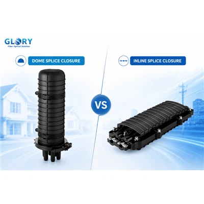
What Is a Horizontal (Inline) Splice Closure?

A horizontal (inline) splice closure has a long, tube-like or flat cylindrical shape with cable entry ports at both ends. Cables enter from one side, are spliced internally, and continue out the opposite side-following the same straight line as the cable itself.
Typical applications:
• Duct and pipeline installations where cables run through predefined conduits
• Direct burial in narrow trenches
• Straight-through splicing of two identical cables
• Repairing damaged cable segments
For long-haul backbone networks where the cable simply continues without branching, inline closures are often the space-efficient choice.
What Is a Dome Splice Closure?
A dome splice closure has a cylindrical, dome-shaped body with all cable entries coming from the bottom. The fibers enter through a single sealed end, are spliced and stored inside the dome, and then exit back through the same end-often to multiple branch cables.
Typical applications:
• Aerial pole-mounted installations (cables enter from the bottom, hang vertically)
• Manholes and handholes (space-efficient vertical placement)
• Wall-mounting in MDU corridors
• Mid-span access where cables are tapped without being cut
Why the dome shape? The curved top naturally sheds water, ice, and debris. It evenly distributes external pressure from burial or water immersion, and the single-end seal is inherently more reliable than sealing two ends.

Key Difference 1: Cable Entry Configuration and Routing
Horizontal (Inline): Two‑Way Entry
With cables entering from both ends, horizontal closures are optimized for straight-through cable runs. This makes them ideal for long-distance trunk lines where the cable just keeps going. However, because cables come from opposite directions, internal fiber routing requires careful planning-especially in confined spaces.
Dome: One-Way Entry
In dome closures, all cables come from a single direction. This simplifies installation for aerial pole mounts (cables enter from below, distribute upward) and makes branch splicing more intuitive. When you need to take one feeder cable and split it into several distribution cables going to different directions, the dome design's unified entry point is a natural fit.
The Fiber Management Advantage
The Fiber Optic Association notes that dome closures are "easier to handle when splicing and storing service loops," and the visual comparison is striking: dome closures keep fibers much neater, especially when re‑entering the closure for moves, adds, and changes.
Key Difference 2: Application Suitability
Horizontal closures excel in:
• Underground ducts: Their elongated shape fits neatly inside narrow conduits.
• Direct burial trenches: The low-profile design can be buried without requiring large excavations.
• Trunk line repairs: When a cable is cut, an inline closure splices it back together without changing the cable's physical footprint.
• Straight-branch point-to-point: An inline design is always the first choice when cables enter and exit from opposite sides.
Dome closures excel in:
• Aerial pole-mounting: Hang the closure from a pole with cables entering from below-natural and gravity-assisted.
• FTTH distribution points: Split one feeder cable into many drop cables going to individual homes or businesses.
• Manhole and handhole installations: Compact footprint fits easily into confined spaces.
• Mid-span access: Tapping a cable without cutting it is much easier with a dome closure.
Key Difference 3: Fiber Capacity and Management
Horizontal Closures: Linear Density
Due to their long, narrow shape, horizontal closures need to carefully route fibers along the length of the closure. This can become complicated for high‑density splicing. The GL09-6809-C handles up to 144 fibers, but because all fiber trays are stacked in a linear arrangement, technicians must manage slack storage carefully to avoid exceeding minimum bend radius requirements.
Dome Closures: Concentric Density
With their circular, domed shape, dome closures arrange splice trays in a stacked, concentric pattern. This makes fiber routing more intuitive and typically offers better access to individual trays without disturbing others. The GL-5601, for example, uses up to 6 stacked trays, each tray holding 24 single fibers (or 72 ribbon fibers), for a total of 144 single fibers (or 432 ribbon fibers). The closure also accommodates up to 1 PLC splitter and 6 ports (1 oval plus 4 round) for flexible cable management, offering a true multi-function splice node in a compact cylindrical footprint.
Key Difference 4: Sealing and Re‑entry
Mechanical Seals (common on both types)
Mechanical seals use gaskets, O-rings, or clamp mechanisms that are compressed by screws or latches, enabling repeated opening without replacing the sealing material.
The GL09-6809-C uses a mechanical sealing system delivering IP68 protection, and its screws, gaskets, and fasteners are made of 304 stainless steel for corrosion resistance. Many horizontal closures also use mechanical seals, allowing easy re-entry for maintenance and upgrades.
Heat-Shrink Seals (more common on dome closures)
Some dome closures, particularly those designed for ultra‑high protection, use heat-shrink seals-creating a permanent, 360° waterproof barrier. The trade-off is that heat-shrink sealed closures cannot be reopened without cutting the sleeve and applying a new one.
Single-End vs. Dual-End Sealing
Dome closures have only one sealing interface (the bottom entry). Horizontal closures have two (both ends). Fewer sealing interfaces mean fewer potential failure points. This fundamental design advantage explains why FOA describes the dome's "single end seal can be more reliable".
Selecting the Right Closure: A Practical Decision Framework

Use a horizontal (inline) closure when:
1.You are splicing two cables in a straight-through configuration (e.g., extending a trunk line).
2.The closure will be installed in a narrow duct, pipeline, or direct burial trench.
3.Space is constrained in the longitudinal direction (e.g., inside a manhole where length matters more than height).
4.Minimal branching is required; you primarily need inline splicing.
5.You require a re-enterable mechanical seal for future maintenance and upgrades.
6.Your priority is fitting the closure into an existing linear infrastructure footprint.
Use a dome closure when:
1.You are branching a feeder cable into multiple distribution cables (e.g., FTTH hub splitting to 8–16 subscribers).
2.The closure will be installed in an aerial location (pole-mounted, strand-hung) or manhole with limited horizontal space.
3.Mid-span access is required-tapping a cable without cutting it.
4.The closure will be opened and closed multiple times over its life (e.g., for adds, moves, changes).
5.You need to integrate passive components like PLC splitters alongside splicing.
6.Your network node requires "splice + termination" multi-function capability.
Practical Guidance: Matching Closure Types to Network Topologies
|
Network Topology |
Recommended Closure Type |
Why |
|
Point to point trunk line (one feeder in, one feeder out) |
Horizontal / Inline |
Straight through configuration fits the closure's natural design. |
|
Point to multipoint distribution (one feeder in, 4–16 drops out) |
Dome |
Single end entry naturally branches to multiple outputs. |
|
Ring topology (two feeders in, two out) |
Both possible |
Mechanical seal inline closures work well; dome also possible with careful cable entry management. |
|
Mid span access tap (cable continues, one fiber tapped out) |
Dome |
Easier fiber routing and management within the dome's spacious interior. |
|
Duct installation (narrow conduit) |
Horizontal / Inline |
Elongated shape fits confined spaces. |
|
Aerial pole mount |
Dome |
Vertical orientation with bottom entry is natural and gravity assisted. |
|
Manhole / handhole |
Both possible |
Dome often more space efficient in square handholes; inline better for long, narrow chambers. |
|
MDU corridor (wall mount) |
Dome |
Compact footprint fits narrow corridor walls. |
Conclusion: Choose by Geometry and Application, Not by Habit
When deciding between horizontal and dome splice closures, let the geometry of the installation and the topology of the network guide your choice, not personal habit or supply availability.
• Horizontal (inline) closures are optimized for straight-line, two-ended cable entries-ideal for duct, direct burial, and trunk line repairs. They excel in constrained linear spaces.
• Dome closures are optimized for one-ended, multi-branch cable entries-ideal for aerial pole mounts, FTTH distribution points, and mid-span access. They excel in complex branching topologies.
Both types, when manufactured to high standards (IP68, GR-771 tested, wide temperature tolerance), provide reliable protection for your fiber splices. But matching the closure design to your actual deployment conditions will save you from unnecessary failures, lower maintenance costs, and extend the life of your outside plant infrastructure.