Why Your Fiber Choice at the Drop Point Costs - or Saves - Thousands
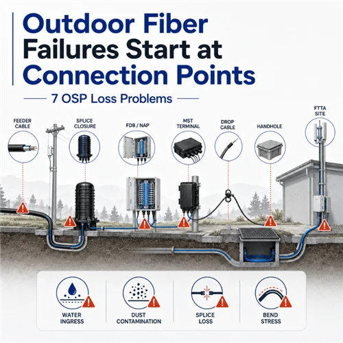
Fiber optic networks fail at the last meter more often than anywhere else. According to field-maintenance records from metropolitan FTTH deployments, approximately 50% of installation and maintenance failures in ODN access networks are caused by a single, preventable mistake: using standard G.652D pigtails to terminate fiber in tight-space distribution boxes and ONT connection points. The problem is not optical incompatibility. It is mechanical. G.652D fiber, when bent sharply - as inevitably happens inside a small splice closure or terminal box - introduces macro-bending loss that can reach 3–8 dB at the 1490 nm GPON downstream wavelength. That turns a clean link into a customer complaint.
Understanding the structural and performance differences between G.652D and the G.657A series is not academic. It directly determines whether your FTTH network runs at specification or generates repeat truck rolls. This guide provides the definitive technical comparison, a field-deployable application decision matrix, splice compatibility data, and a cost analysis that goes beyond per-meter price to total cost of ownership.
What Is G.652D Fiber? Structure, Specs, and Where It Belongs
G.652D is the most widely deployed single-mode optical fiber in the world. It is the 'D' sub-category of ITU-T G.652 - the latest revision, which added a low water peak requirement (attenuation at 1383 nm must not exceed the value at 1310 nm, even after hydrogen aging). This makes G.652D compatible with CWDM transmission systems operating across the full 1310–1625 nm spectrum.
Structurally, G.652D uses the classic 9/125 µm core-to-cladding design with a step-index or very slightly depressed refractive index profile. This geometry is optimized for long, straight transmission paths. The Mode Field Diameter (MFD) - the effective diameter over which roughly 86% of optical power is guided - is nominally 9.2 µm at 1310 nm.

G.652D Full Specification Table
|
Parameter |
G.652D Value |
Notes |
|
Attenuation @ 1310 nm |
≤ 0.35 dB/km |
ITU-T G.652D § 4.1 |
|
Attenuation @ 1550 nm |
≤ 0.20 dB/km |
ITU-T G.652D § 4.1 |
|
Attenuation @ 1383 nm (water peak) |
≤ value at 1310 nm |
Low water peak - CWDM compatible |
|
Macrobend loss @ 30 mm radius × 100 turns |
≤ 0.5 dB @ 1625 nm |
Minimum bend radius specification |
|
Mode Field Diameter (MFD) @ 1310 nm |
9.2 ± 0.4 µm |
Core to matching G.657A |
|
Polarization Mode Dispersion (PMD) |
≤ 0.2 ps/√km |
Link design value |
|
Operating wavelength range |
1260–1625 nm |
Full O to L band |
|
Zero-dispersion wavelength |
1300–1324 nm |
Standard SSMF characteristic |
G.652D is the correct fiber for outside-plant (OSP) feeder cables, metropolitan area network (MAN) trunks, long-haul underground conduit runs, and data center inter-building fiber where routes are planned for minimal bends. Its limitation becomes critical only where the network architecture demands tight routing: indoor walls, splice closures, terminal boxes, and ONT termination points.
What Is G.657A Fiber? The Bend-Insensitive Standard Explained
G.657 is the ITU-T standard specifically designed for fiber-to-the-home (FTTH) access networks and any deployment environment where tight bends are unavoidable. The key engineering innovation is a modified refractive index profile - typically a trench-assisted design with a depressed cladding layer that more tightly confines light to the core, significantly reducing macro-bending loss even at very small bend radii.
G.657 is divided into two categories: Category A (G.657A) is fully backward-compatible with G.652D and can be used throughout the entire access network. Category B (G.657B) is NOT compatible with G.652D and is restricted to short-reach, in-building deployments under 1 km. For the vast majority of FTTH and telecom deployments, G.657A is the relevant standard.
G.657A1 vs G.657A2 - Key Differences
|
Parameter |
G.657A1 |
G.657A2 |
|
Minimum bend radius |
10 mm |
7.5 mm |
|
Macrobend loss @ min. radius (1 turn) |
≤ 0.2 dB @ 1550 nm |
≤ 0.5 dB @ 1550 nm / ≤ 1.0 dB @ 1625 nm |
|
G.652D backward compatibility |
✓ Full (Cat A) |
✓ Full (Cat A) |
|
MFD @ 1310 nm |
9.2 ± 0.4 µm |
9.2 ± 0.4 µm |
|
Attenuation @ 1310/1550 nm |
≤ 0.35 / ≤ 0.20 dB/km |
≤ 0.35 / ≤ 0.20 dB/km |
|
Refractive index profile |
Trench-assisted |
Trench-assisted (deeper trench) |
|
Typical application |
Wall conduit, riser, FTTA |
FTTH drop, ONT termination, MDU |
|
Relative cost vs G.652D |
~10–15% premium |
~15–25% premium |
The deeper trench in G.657A2's refractive index profile is what enables the 7.5 mm minimum bend radius. This trench acts as a barrier, reflecting light back into the core rather than allowing it to scatter outward. The result is a fiber that can be routed around tight corners inside a terminal box, coiled in an ONT housing, or pulled through narrow wall conduits without accumulating meaningful signal loss.
G.652D vs G.657A - The Definitive Head-to-Head Comparison
|
Parameter |
G.652D |
G.657A1 |
G.657A2 |
|
Minimum bend radius |
30 mm (100 turns, ≤0.5 dB) |
10 mm (1 turn, ≤0.2 dB) |
7.5 mm (1 turn, ≤0.5 dB) |
|
Attenuation @ 1550 nm |
≤ 0.20 dB/km |
≤ 0.20 dB/km |
≤ 0.20 dB/km |
|
Attenuation @ 1310 nm |
≤ 0.35 dB/km |
≤ 0.35 dB/km |
≤ 0.35 dB/km |
|
MFD @ 1310 nm |
9.2 ± 0.4 µm |
9.2 ± 0.4 µm |
9.2 ± 0.4 µm |
|
G.652D compatible |
✓ (is G.652D) |
✓ Full (Cat A) |
✓ Full (Cat A) |
|
CWDM / water peak |
✓ (G.652D) |
✓ |
✓ |
|
Typical IL (field run) |
0.20 dB/km |
0.20 dB/km |
0.20 dB/km |
|
Cost index (per meter) |
1.00× |
~1.10–1.15× |
~1.15–1.25× |
|
Primary use case |
OSP trunk, backbone |
Wall conduit, FTTA |
FTTH drop, MDU, ONT |
|
Bend failure risk (indoor) |
HIGH |
LOW |
VERY LOW |
The table reveals the counterintuitive truth: G.652D, G.657A1, and G.657A2 have essentially identical attenuation and transmission characteristics on a straight run. The entire practical difference is bend performance. Choosing the wrong fiber for a bend-intensive environment does not mean 'slightly more loss' - it means potential link failures and expensive re-work.
Macro-Bending Loss: The Physics Behind the Difference
When an optical fiber is bent, the outer edge of the guided mode travels a longer path than the inner edge. Beyond a critical radius, the evanescent field - the portion of the optical field that extends slightly beyond the core - can no longer be guided and radiates outward. This is macro-bending loss. G.652D's step-index profile offers relatively weak confinement at large bending radii, making it sensitive to this effect at the radii common in terminal boxes and indoor routing.
G.657A2's trench-assisted profile adds a ring of lower refractive index between the core and the outer cladding. This ring acts as a mirror layer, reflecting escaping light back into the core and suppressing macro-bending loss even at 7.5 mm radius - four times tighter than G.652D's minimum specification.
Splice Compatibility: Can You Mix G.652D and G.657A Fiber?
Yes - and this is one of the most misunderstood aspects of the G.657 standard. Because G.657A is defined as backward-compatible with G.652D (the ITU-T 'Cat A' designation exists specifically to ensure this), the two fibers share essentially identical Mode Field Diameters. Light transitions from one to the other at a splice point without encountering a significant refractive boundary.
Splice Loss by Combination
|
Splice Combination |
Typical Splice Loss |
Notes |
|
G.652D - G.652D |
0.01–0.02 dB |
Standard baseline |
|
G.652D - G.657A1 |
0.01–0.03 dB |
MFD match: near-zero loss |
|
G.652D - G.657A2 |
0.01–0.03 dB |
MFD match: near-zero loss |
|
G.657A1 - G.657A2 |
0.01–0.02 dB |
Same MFD family |
|
G.652D - G.657B3 |
Not recommended |
B-series NOT G.652D compatible |
Splicer Settings: No Special Configuration Required
When using a modern core-alignment fusion splicer (Fujikura 70S/80S, Sumitomo Type-82, Inno IFS-15, or equivalent), leave the machine on AUTO or standard SM (single-mode) mode. The splicer's CCD cameras will automatically detect and align both cores. No manual parameter adjustment is needed. The resulting splice loss will be within 0.01–0.03 dB - well below the 0.1 dB industry threshold and fully within ITU-T G.652 link budget.
Important physical handling note: G.652D is structurally more brittle when bent tightly. Even after achieving a clean optical splice between G.652D and G.657A2, the G.652D segment remains at risk of mechanical failure if routed through a tight space. The splice is optically sound; the cable routing is the engineering constraint.
Application Decision Matrix: Which Fiber for Which Segment?
Use this matrix to specify the correct fiber for each segment of your network. Choosing by segment rather than by price or familiarity eliminates the vast majority of FTTH deployment failures.
|
Network Segment |
Recommended Fiber |
Reason |
Engineering Note |
|
OSP Feeder Trunk (underground) |
G.652D |
Long straight runs, duct-protected, no sharp bends |
Cost-optimal for volume |
|
Aerial Self-Supporting Cable |
G.652D or G.657A1 |
Figure-8 with messenger wire; moderate bends at poles |
G.657A1 if tight pole-wrap required |
|
Riser / Vertical Building Cable |
G.657A1 |
Wall conduit; moderate routing bends |
LSZH jacket for fire code |
|
FTTH Indoor Last-Drop |
G.657A2 |
ONT termination, distribution box, wall routing |
G.657A2 mandatory; pre-terminated preferred |
|
5G FTTA Antenna Cable |
G.657A1 armored |
Tower-top RRU to BBU; outdoor exposure + bends |
Armored jacket for mechanical protection |
|
Data Center Intra-Rack |
G.657A2 |
Tight bend radii in patch panels and cable managers |
Also use for MPO trunk modules |
|
MDU In-Building Distribution |
G.657A2 |
Apartment building risers and drop points |
Factory-terminated recommended |
|
Long-Haul / Backbone (100+ km) |
G.652D |
DWDM, CWDM; straight runs, amplified spans |
G.657 offers no advantage; unnecessary cost |
The Pre-Terminated Drop Cable Argument
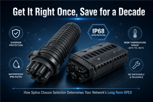
If 50% of FTTH network failures originate at the pigtail-to-drop-cable splice point, and if that splice point uses G.652D pigtails in a tight distribution box, the engineering solution is straightforward: eliminate the field splice entirely. Pre-terminated G.657A2 drop cables - factory-assembled with SC/APC or Sticklok connectors, 100% insertion-loss tested before shipping, and supplied with OTDR trace reports - remove the field technician's ability to introduce a bend-sensitive G.652D segment into a bend-intensive environment.
At Glory Optical Communication, our pre-terminated G.657A2 FTTH drop cables and Sticklok termination boxes are specifically designed for this purpose. Every assembly leaves our factory with IL ≤ 0.5 dB and a pass certificate. Installation becomes plug-and-play: click the Sticklok connector into the terminal box. No splicing. No epoxy. No polishing. No bend failures.
Frequently Asked Questions
Q: Is G.657A fully backward-compatible with G.652D?
A: G.657 Category A (G.657A1 and G.657A2) is fully backward-compatible with G.652D. Their Mode Field Diameters are matched, and they can be fusion-spliced with 0.01–0.03 dB loss. G.657 Category B (G.657B2 and G.657B3) is NOT compatible with G.652D and should only be used in short-reach, in-building deployments under 1 km.
Q: What does G.657A2 mean exactly?
A: G.657A2 designates an ITU-T single-mode optical fiber standard: G.657 is the series (bend-insensitive single-mode fiber); A indicates Category A (G.652D backward-compatible); 2 indicates Sub-category 2, which specifies a minimum bend radius of 7.5 mm (tighter than A1's 10 mm). G.657A2 is the standard used in the vast majority of modern FTTH drop cables globally.
Q: Can I use G.657A2 for long-haul runs to save money on multiple fiber types?
A: Technically yes - G.657A2 has identical attenuation to G.652D on straight runs. Practically, no: G.657A2 costs 15–25% more per meter, and that premium buys you bend-insensitivity that a feeder trunk in an underground duct simply does not need. Reserve G.657A2 for bend-intensive indoor and access segments; use G.652D for trunk and backbone to manage cost.
Q: Does G.657A support GPON and XGS-PON networks?
A: Yes. Both GPON (1310/1490/1550 nm) and XGS-PON (1270/1577 nm) operate well within G.657A's specified wavelength range of 1260–1625 nm. G.657A2 is in fact the preferred fiber for XGS-PON last-mile drops because the 1577 nm downstream wavelength is in the L-band where macro-bending sensitivity is highest - exactly where G.657A2's bend performance advantage is most critical.
Q: What is macro-bending loss and why does G.652D suffer from it more?
A: Macro-bending loss occurs when a fiber is bent at a radius large enough that the optical mode's evanescent field can no longer be fully guided and radiates outward. G.652D's simple step-index profile provides relatively weak optical confinement, making it sensitive to this effect at the radii (7.5–30 mm) common in terminal boxes and wall routing. G.657A2's trench-assisted profile adds a depressed-index ring between core and cladding that acts as a mirror, reflecting escaping light back into the core and suppressing macro-bending loss by orders of magnitude at equivalent radii.